Plate-fin heat exchanger

A technology of plate-fin heat exchanger and fin heat exchanger, applied in the direction of heat exchanger type, heat exchanger shell, indirect heat exchanger, etc., can solve the problem of reducing the heat exchange performance, internal Uneven distribution of logistics and other problems, to achieve the effect of improving heat exchange performance and improving uniformity

Inactive Publication Date: 2010-04-21
WUXI JIALONG HEAT EXCHANGER
View PDF0 Cites 19 Cited by
  • Summary
  • Abstract
  • Description
  • Claims
  • Application Information

AI Technical Summary

Problems solved by technology

[0003] The present invention aims at the extremely uneven internal flow distribution of the head cavity structure of the plate-fin heat exchanger in the prior art, which reduces the heat exchange performance of the plate-fin heat exchanger, and provides a simple structure, low cost low plate fin heat exchanger

Method used


Image

  • Plate-fin heat exchanger
  • Plate-fin heat exchanger
  • Plate-fin heat exchanger

Examples


Embodiment 1

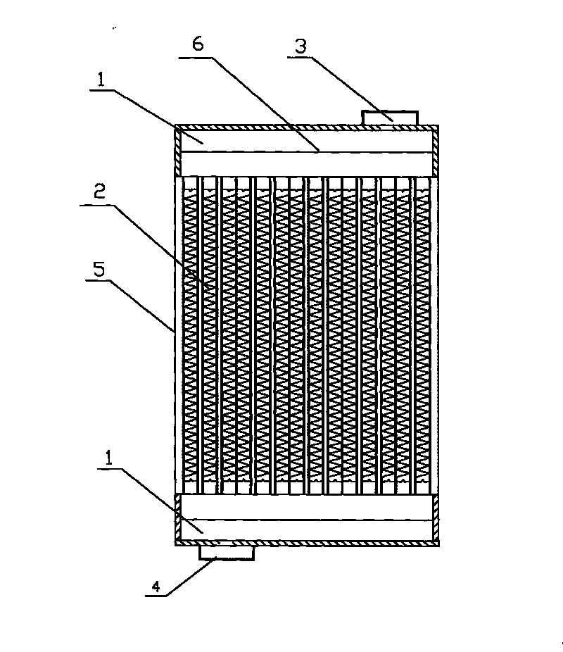
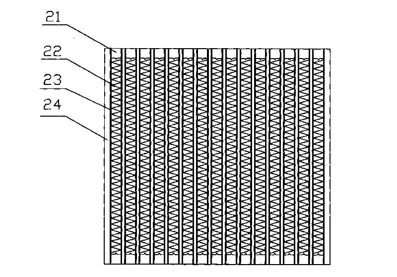
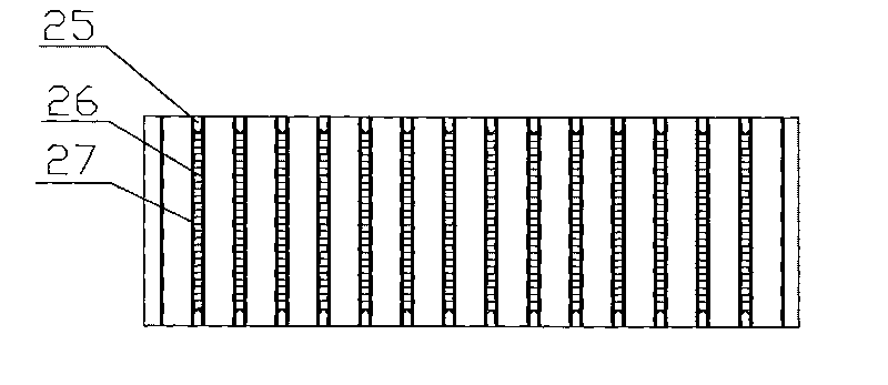
[0018] A plate-fin heat exchanger, such as figure 1 , figure 2 , image 3 and Figure 5 As shown, it includes a casing 4, a fixing part mounted on the casing 4 for fixing the plate-fin heat exchanger, a heat exchange core 2 and a head cavity 1 welded on both ends of the heat exchange core 2, the head cavity The body 1 is welded with an inlet pipe 3 and an outlet pipe 4, and the heat exchange core 2 includes an outer baffle 23, an inner baffle 27, an inner fin 26, an inner seal 25, an outer fin 22, an outer seal 21 and the sides on both sides. The plate 24, the outer fins 22 and the outer seals 21 placed between the outer partitions 23 and the outer partitions 23 form a cold channel, and the inner fins 26 and the inner seals 25 placed between the inner partitions 25 and the inner partitions 25 constitute a hot channel , the head cavity 1 is communicated with the hot aisle, the cold aisle and the hot aisle are placed in layers and crossed, the head cavity 2 has a perforated...

Embodiment 2

[0020] A plate-fin heat exchanger, such as figure 1 , figure 2 , image 3 and Figure 5 As shown, it includes a casing 4, a fixing part mounted on the casing 4 for fixing the plate-fin heat exchanger, a heat exchange core 2 and a head cavity 1 welded on both ends of the heat exchange core 2, the head cavity The body 1 is welded with an inlet pipe 3 and an outlet pipe 4, and the heat exchange core 2 includes an outer baffle 23, an inner baffle 27, an inner fin 26, an inner seal 25, an outer fin 22, an outer seal 21 and the sides on both sides. The plate 24, the outer fins 22 and the outer seals 21 placed between the outer partitions 23 and the outer partitions 23 form a cold channel, and the inner fins 26 and the inner seals 25 placed between the inner partitions 25 and the inner partitions 25 constitute a hot channel , the head cavity 1 is connected with the hot aisle, the cold aisle and the hot aisle are placed in layers and crossed, and a staggered row of uneven punchin...


PUM


Abstract

The invention relates to heat exchange equipment and discloses a plate-fin heat exchanger. The plate-fin heat exchanger comprises a shell, a fixing part arranged on the shell and used for fixing the plate-fin heat exchanger, a heat exchange core and an end socket cavity welded at two ends of the heat exchange core, wherein the end socket cavity is welded with an inlet pipe and an outlet pipe; the heat exchange core comprises outside clapboards, inside clapboards, an inside fin, an inside seal, an outside fin, an outside seal and bilateral side plates; the outside fin and the outside seal arranged between the outside clapboards forms a cold passageway ; the inside fin and the inside seal arranged between the inside clapboards forms a hot passageway; the end socket cavity is communicated with the hot passageway; the cold passageway and the hot passageway are arranged in a layered crossing way; the inside of the end socket cavity is provided with a punching baffle, and holes with diameters from small to large are distributed along a central axis of the punching baffle from inside to outside. The structure improves the uniformity of flow velocity distribution of outlet cross-section of the whole plate and improves the heat exchange performance of the heat exchanger.

Description

technical field [0001] The invention relates to a heat exchange device, in particular to a plate-fin heat exchanger. Background technique [0002] The plate-fin heat exchanger has the characteristics of compact structure and high heat transfer efficiency. Compared with the traditional shell and tube heat exchanger, its heat transfer efficiency is increased by 20-30%, and the cost can be reduced by 50%. It is now widely used in air However, due to the unreasonable design, manufacture and structure of plate-fin heat exchangers, the distribution of internal logistics and temperature distribution of heat exchangers is uneven, which affects the heat exchange efficiency of plate-fin heat exchangers. main factor. At present, the internal flow distribution of the head structure of common plate-fin heat exchangers is extremely uneven, such as Figure 4 For the baffle in the head structure shown, the flow velocity distribution at the outlet of the plate-fin heat exchanger shows a cer...

Claims


Application Information

Patent Timeline
Patent Type & Authority Applications(China)
IPC IPC(8): F28D1/03F28F9/22
Inventor 金春花
Owner WUXI JIALONG HEAT EXCHANGER
Why Eureka
Try Eureka