Spring self-limit filler cap

A fuel filler cap and spring limit technology, which is applied in the field of automobile body design, can solve the problem of easy rebound of the fuel filler cap and achieve the effect of eliminating the impact

Inactive Publication Date: 2010-04-28
CHERY AUTOMOBILE CO LTD
View PDF6 Cites 2 Cited by
  • Summary
  • Abstract
  • Description
  • Claims
  • Application Information

AI Technical Summary

Problems solved by technology

[0003] The purpose of the present invention is to provide a spring self-limiting fuel filler cap, which solves the problem that the fuel filler cap in the prior art is easy to rebound when it is opened

Method used


Image

  • Spring self-limit filler cap
  • Spring self-limit filler cap
  • Spring self-limit filler cap

Examples


Embodiment Construction

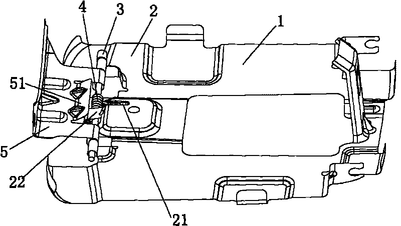
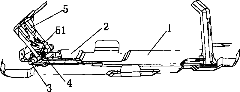
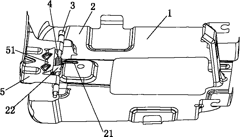
[0011] Such as figure 1 with figure 2 As shown, the spring self-limiting fuel filler cap in this specific embodiment includes: fuel filler cap outer plate 1 , fuel filler cap inner plate 2 , rotating shaft 3 , spring 4 , and rotating leaf plate 5 . The inner panel 2 of the fuel filler cap is provided with a spring fixing groove 21 and a spring limiting block 22 . The spring fixing groove 21 can be stamped out together when making the inner panel 2 of the fuel filler cap. The spring limiter 22 can be integrally formed with the fuel filler cap inner plate 2, for example, the spring limiter 22 can be stamped and bent together when making the fuel filler cap inner plate 2; of course, the spring limiter 22 can also be Make it separately, and then be fixedly connected with the inner panel 2 of the fuel filler cap.

[0012] A spring touch plate 51 is arranged on the rotating leaf plate 5 . The spring touch plate 51 is integrally formed with the rotating leaf plate 5, for example...


PUM


Abstract

The invention relates to a spring self-limit filler cap, comprising a filler cap outer board, a filler cap inner board, a rotating shaft, a spring, a rotating leaf plate, a spring limit block and a spring touch board; the spring limit block is fixedly connected with the filler cap inner board, and the rotating end of the spring is pressed on the spring limit block before the filler cap is opened with a certain angle or after the filler cap is closed with a certain angle; the spring touch board is fixedly connected with the rotating leaf plate, and the rotating end of the spring is pressed on the spring touch board before the filler cap is opened with a certain angle or after the filler cap is closed with a certain angle; by adopting the spring self-limit filler cap in the technical proposal, as the rotating end of the spring is pressed on the spring limit block before the filler cap is opened with a certain angle or after the filler cap is closed with a certain angle, the spring force can not act on the rotating leaf plate all the time, in particular to the later period that the filler cap is opened, the spring force can not act on the rotating leaf plate, and back force of the spring can not be generated.

Description

technical field [0001] The invention relates to the technical field of automobile body design, in particular to an automobile fuel filler cap, in particular to a spring self-limiting fuel filler cap. Background technique [0002] The oil filler cap of existing automobile mostly adopts the structural form that a coil spring is installed between the fuel filler lid inner plate and the rotating leaf plate at present, and utilizes the elastic force of the coil spring to open the fuel filler lid. When the oil filler cap is baked in the paint shop, the elastic force of the spring is partially attenuated. In addition, in the actual operation and use, repeated opening will also cause the spring elastic force to gradually attenuate and become invalid; therefore, it is necessary to increase the helical force in the design. Spring force to compensate for spring force decay. However, the existing fuel filler cap is affected by the spring force during the whole process of opening, and i...

Claims


Application Information

Patent Timeline
Patent Type & Authority Applications(China)
IPC IPC(8): B60K15/05
Inventor 方传运席艳秋马保林
Owner CHERY AUTOMOBILE CO LTD
Why Eureka
Try Eureka