Novel stop band gap ultra wide band antenna

An ultra-wideband antenna and slot technology, which is applied to slot antennas, antennas, electrical components, etc., can solve the problems of non-steep, small size, and steep stop-band, and achieve the effect of good filtering effect, small size, and easy adjustment.

An ultra-wideband antenna and slot technology, which is applied to slot antennas, antennas, electrical components, etc., can solve the problems of non-steep, small size, and steep stop-band, and achieve the effect of good filtering effect, small size, and easy adjustment.

CN101699655AInactive Publication Date: 2010-04-28SOUTH CHINA UNIV OF TECH

Image

  • Novel stop band gap ultra wide band antenna
  • Novel stop band gap ultra wide band antenna
  • Novel stop band gap ultra wide band antenna

Examples


Embodiment

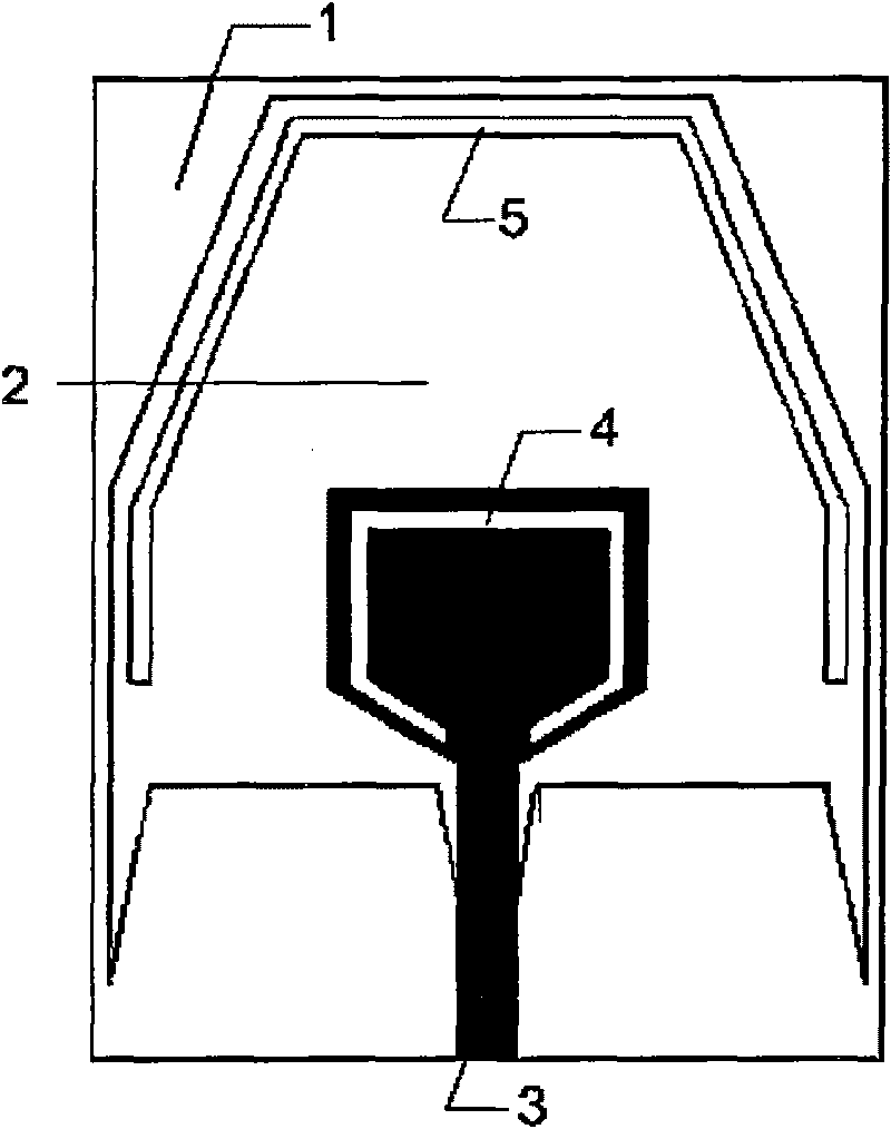
[0025] The structure of the novel stopband slot ultra-wideband antenna of the present invention is as follows: figure 1 As shown, it includes: a rectangular dielectric board 1 and metal printed antennas located on both sides of the rectangular dielectric board 1; a polygonal first slit 2 is opened on the front of the rectangular dielectric board 1, and the first slit 2 is a closed curve. The circumference of a slot 2 is 90 mm, and the polygonal slot 2 is the radiation unit of the antenna; the T-shaped microstrip feeder 3 with a gradient structure located on the back of the rectangular dielectric plate 1 is used as the feeder unit of the antenna, above the T-shaped microstrip feeder 3 The position of the platform feeder corresponds to the front of the rectangular dielectric plate 1, which is in the middle and lower part of the delineated range of the first slot 2. The above-mentioned radiation unit 2 and the feed unit 3 form a polygonal slot antenna. Adjust the polygonal slot 2 ...


PUM


Abstract

The invention discloses a novel stop band gap ultra wide band antenna, wherein the antenna comprises a polygan gap antenna and a combined trap wave structure, namely, a combined trap wave is generated by opening a C-shaped gap on the T-shaped micro-strip feeder which serves as a feed unit and adding micro-strip wires in the polygan gap. The polygan gap antenna can generate ultra wide band characteristics and adopts a double frequency resonance oscillation trap wave structure similar to a second order filter to realize narrower stop band. Compared with the prior art, the stop band ultra wide band antenna can realize good filtering characteristics and has the advantages of small size and low cost.

Description

technical field [0001] The invention relates to an ultra-wideband (UWB) antenna, in particular to a novel stopband slot UWB antenna. Background technique [0002] Ultra-wideband (UWB) technology originated from the pulse communication technology that emerged in the 1960s. It uses ultra-short pulses with extremely wide spectrum for communication, also known as baseband communication and carrier-free communication. It is mainly used in military radar, positioning and communication systems. . In February 2002, the U.S. Federal Communications Commission (FCC) opened the 3.1GHz-10.6GHz frequency band to ultra-wideband communications, and approved UWB technology for civilian use; subsequently, Japan opened the ultra-wideband frequency band in August 2006. Because UWB technology has the characteristics of high transmission rate (1Gbit / s), strong anti-multipath ability, low power consumption, low cost, strong penetration ability, low probability of interception, and sharing spectru...

Claims


Application Information

Patent Timeline
28 Apr 2010
Publication
CN101699655A
IPC
H01Q13/08; H01Q13/10
Inventors
褚庆昕; 叶亮华