High voltage feed vacuum state device with motion compensation

A motion compensation, high-voltage technology, applied in accelerators, electrical components, etc., can solve problems such as hardening, poor reliability, and fracture, and achieve the effect of eliminating motion resistance, high transmission voltage, and small volume

Active Publication Date: 2012-02-08
INST OF MODERN PHYSICS CHINESE ACADEMY OF SCI
View PDF0 Cites 0 Cited by
  • Summary
  • Abstract
  • Description
  • Claims
  • Application Information

AI Technical Summary

Problems solved by technology

[0002] At present, in the field of electric vacuum, there are many situations where it is necessary to form a high-voltage electric field with motion compensation in a vacuum state. In order to make the high-voltage feed-in line compensate for the translational and rotational motion of the electric field in the plane, the traditional method is to make the high-voltage feed-in line Made into a wavy shape, it is not only prone to local hardening and fracture during use, and has poor reliability, but also increases the movement resistance of the high-voltage electrode and its driving device, which affects the accuracy of the high-voltage electric field movement

Method used


Image

  • High voltage feed vacuum state device with motion compensation
  • High voltage feed vacuum state device with motion compensation
  • High voltage feed vacuum state device with motion compensation

Examples


Embodiment Construction

[0013] Below in conjunction with the preferred embodiment shown in accompanying drawing, be described in further detail:

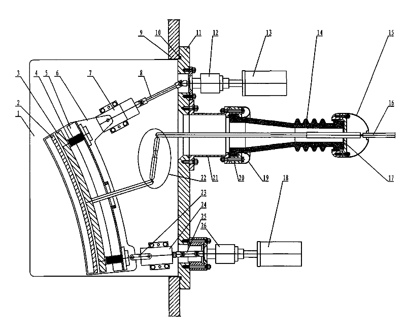
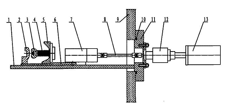
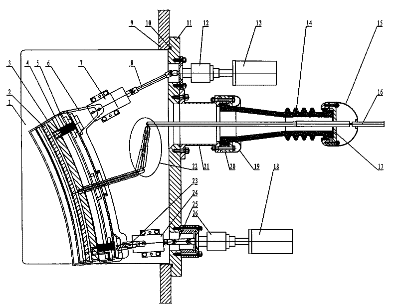
[0014] See figure 1 , 2 , 3, 4, 5, the described high-voltage feed-in vacuum device with motion compensation includes a high-voltage feed-in conductive rod 22, and its feature is that the conductive rod 22 is located in the vacuum cavity 9, and the conductive rod 22 One end is connected to the high-voltage electrode 3, and a ground electrode 2 is provided corresponding to the high-voltage electrode 3. The other end of the conductive rod 22 passes through the transition sleeve 21 and the outer insulating ceramic 14 to connect to the high-voltage output piece 16. The transition sleeve 21 is installed in the vacuum chamber through the flange 11. 9, one end of the outer insulating ceramic 14 is connected to the transition sleeve 21 through a pressure ring 20 and bolts, the other end of the outer insulating ceramic 14 is equipped with a gland 17, and the two e...


PUM


Abstract

The invention mainly relates to a high voltage feeding vacuum state device with motion compensation. It includes a high-voltage feeding conductive rod (22), the conductive rod (22) is located in the vacuum cavity (9), one end of the conductive rod (22) is connected to the high-voltage electrode (3), and a ground electrode ( 2), the other end of the conductive rod (22) passes through the transition sleeve (21) and the outer insulating ceramic (14) to connect the high-voltage output piece (16), and the transition sleeve (21) is installed in the vacuum chamber (9) through the flange (11) ), one end of the outer insulating ceramic (14) is connected to the transition sleeve (21) through a pressure ring (20) and bolts, the other end of the outer insulating ceramic (14) is equipped with a gland (17), and the two ends of the outer insulating ceramic (14) The ends are respectively provided with a shielding ring (19) and a shielding ball (15). It eliminates the additional movement resistance of the high-voltage electrode and its driving device, realizes precise control of the movement of the high-voltage electric field, and has the characteristics of flexibility, reliability, high vacuum, small size, and high transmission voltage.

Description

Technical field: [0001] The present invention mainly relates to the technical field of high-voltage feeder devices required to form a high-voltage electric field with motion compensation in the field of electric vacuum, and in particular to a high-voltage feed-in vacuum device with motion compensation. Background technique: [0002] At present, in the field of electric vacuum, there are many situations where it is necessary to form a high-voltage electric field with motion compensation in a vacuum state. In order to make the high-voltage feed-in line compensate for the translational and rotational motion of the electric field in the plane, the traditional method is to make the high-voltage feed-in line Made into a wavy shape, it is not only prone to local hardening and fracture during use, and has poor reliability, but also increases the movement resistance of the high-voltage electrode and its driving device, which affects the accuracy of the high-voltage electric field move...

Claims


Application Information

Patent Timeline
Patent Type & Authority Patents(China)
IPC IPC(8): H05H7/02
Inventor 张小奇马力祯
Owner INST OF MODERN PHYSICS CHINESE ACADEMY OF SCI
Why Eureka
Try Eureka