Train deicer

A technology for trains and nozzles, which is applied in the direction of railway auxiliary equipment, etc. It can solve the problems of low efficiency, damage to the connection parts of the bogie and the car end, and long time, and achieve the effects of convenient use, thorough deicing, and low energy consumption

Active Publication Date: 2010-05-05
WEIHAI GUANGTAI AIRPORT EQUIP CO LTD
View PDF0 Cites 7 Cited by
  • Summary
  • Abstract
  • Description
  • Claims
  • Application Information

AI Technical Summary

Problems solved by technology

[0002] At present, the traditional deicing methods are to use locomotives to melt naturally in the warehouse, or use hot air to blow, or use high-pressure hot water to flush. Natural melting, hot air, etc. take a long time and have low efficiency. It is composed of a water tank, a catheter and a high-pressure nozzle. There is a pressure pump in the water storage tank, and an electric heater is installed on the water storage tank. When in use, the pressure pump and the electric heater are connected to the power supply. The hot water is directly aimed at the bogie of the train and the connecting parts of the car end. The disadvantage is that the use of high-pressure hot water for deicing will cause great damage to the bogie and the connecting parts of the car end of the train.

Method used


Image

  • Train deicer
  • Train deicer
  • Train deicer

Examples


Embodiment Construction

[0013] Below in conjunction with accompanying drawing, the present invention is further described:

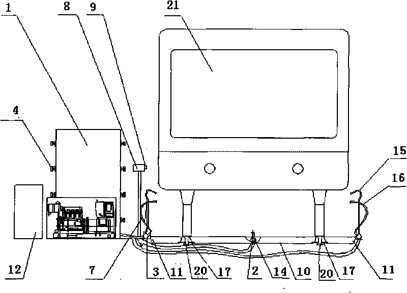
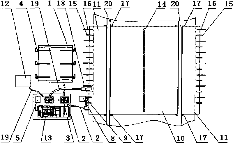
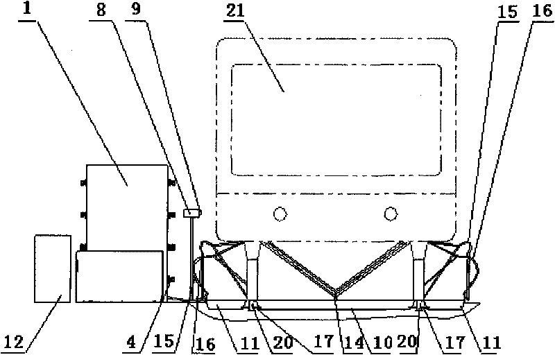
[0014] A train deicing device is provided with a liquid storage tank 1, a catheter 2 and a spray head, the liquid storage tank 1 is provided with a pressure pump 3, and the liquid storage tank 1 is provided with an electric heater 4, which is characterized in that it is equipped with an electric Control system 5, spray rack 6, pole 7, position sensing electric control box 8, position sensor 9, inner waste liquid collection tank 10, outer waste liquid collection tank 11, waste liquid recovery tank 12 and waste liquid recovery liquid pump 13 , an inner waste liquid collection tank 10 is provided between the two rails 20, and an outer waste liquid collection tank 13 is respectively provided on both sides. The outer side of the collection tank 13 is provided with spray racks 6, and the spray racks 6 are arranged in sequence along the rail direction. The two rows of spray racks 6 ar...


PUM


Abstract

The invention discloses a train deicer, which is provided with a liquid storage tank, a liquid guiding pipe and nozzles, wherein the liquid storage tank is provided with a pressure pump inside and an electric heater above. The train deicer is characterized by being provided with an electric control system, spray frames, a prop, a position sensing electric-control box, a position sensor, an inner waste liquid collecting tank, outer waste liquid collecting tanks, a waste liquid recovering box and a waste liquid recovering liquid pump, wherein the inner waste liquid collecting tank is arranged between two rails and the outer waste liquid collecting tanks are respectively arranged on the two sides of the two rails; vertical nozzles are uniformly arranged along the rail direction in the middle of the inner waste liquid collecting tank; the spray frames are arranged outside the outer waste liquid collecting tanks, and the two rows of spray frames are correspondingly provided with high-order deicing nozzles and provided with low-order deicing nozzles corresponding to in the lower parts of the high-order deicing nozzles; waste liquid communicating pipes are arranged outside the inner waste liquid collecting tank, one ends of the waste liquid communicating pipes are connected with the inner waste liquid collecting tank and the other ends are connected with the outer waste liquid collecting tanks which are provided with waste liquid suction holes above; and the waster liquid recovering box and the waste liquid recovering liquid pump are arranged beside the outer waster liquid collecting tanks. The invention has the advantages of novel structure, convenient usage, high deicing efficiency, complete deicing, environmental protection without pollution and the like.

Description

technical field [0001] The invention relates to locomotive auxiliary equipment, in particular to a train deicing device. Background technique [0002] At present, the traditional deicing methods are to use locomotives to melt naturally in the warehouse, or use hot air to blow, or use high-pressure hot water to flush. Natural melting, hot air, etc. take a long time and have low efficiency. It is composed of a water tank, a catheter and a high-pressure nozzle. There is a pressure pump in the water storage tank, and an electric heater is installed on the water storage tank. When in use, the pressure pump and the electric heater are connected to the power supply. The hot water is directly aimed at the bogie of the train and the car-end connection part to rush, and its deficiency is: adopt high-pressure hot water for deicing, and the bogie of the train and the car-end connection part are damaged greatly. Contents of the invention [0003] The object of the present invention is...

Claims


Application Information

Patent Timeline
Patent Type & Authority Applications(China)
IPC IPC(8): B61K13/00
Inventor 林海芸都奎江刘海涛
Owner WEIHAI GUANGTAI AIRPORT EQUIP CO LTD
Why Eureka
Try Eureka