
Undercurrent external heat exchanger bed of circulating fluidized bed

A circulating fluidized bed, external technology, applied in the field of large circulating fluidized bed boilers, can solve the problems of poor heat transfer performance, serpentine tube abrasion and vibration, etc., to improve flow and heat transfer performance, reduce serious vibration, The effect of improving the overall heat transfer performance

Active Publication Date: 2011-04-27
TSINGHUA UNIV
View PDF0 Cites 0 Cited by
  • Summary
  • Abstract
  • Description
  • Claims
  • Application Information

AI Technical Summary

Problems solved by technology

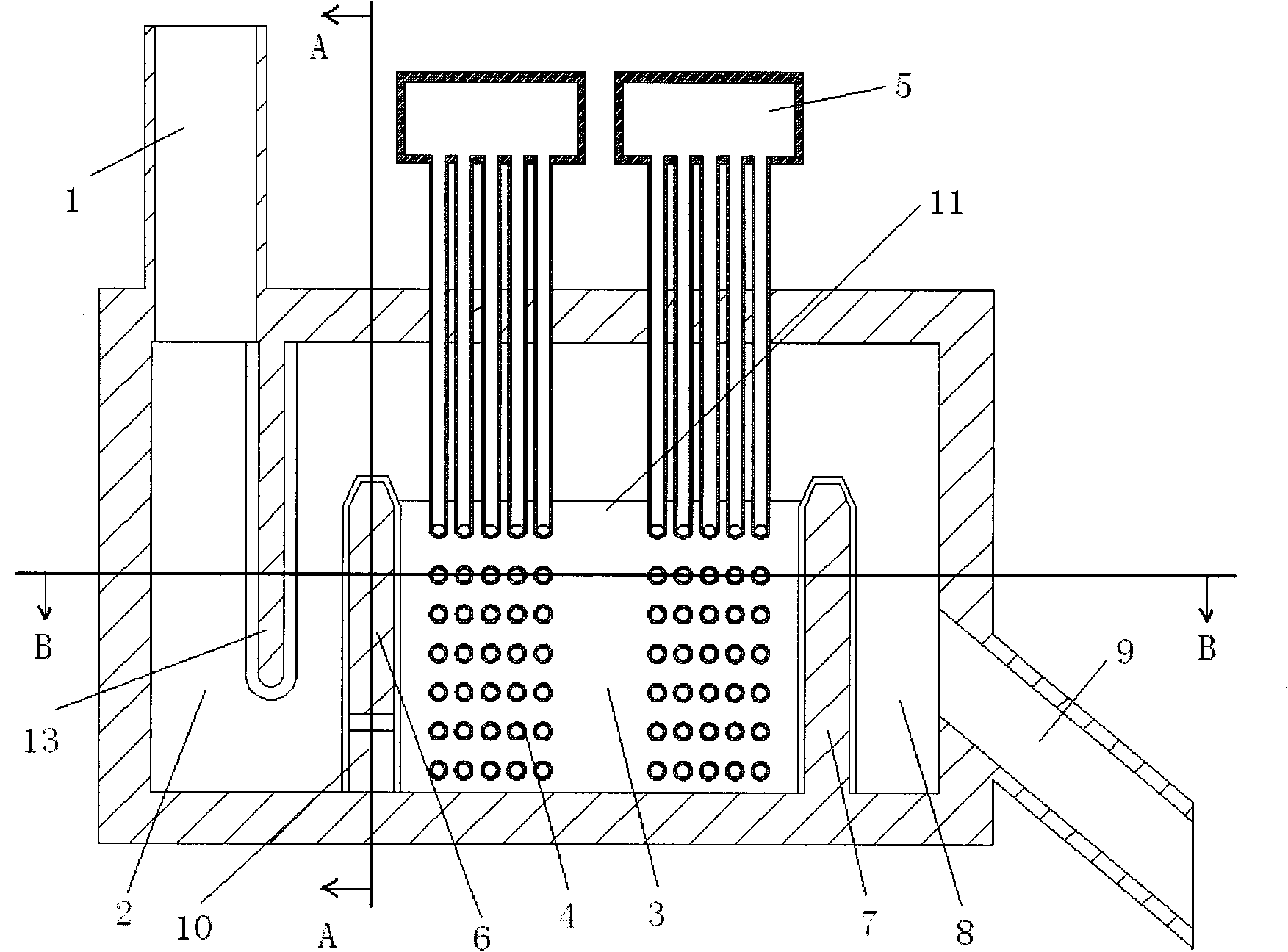
[0004] Aiming at the serious abrasion and vibration of serpentine tubes on the heat exchange surface of the existing external heat exchange bed and poor heat exchange performance, the present invention proposes an improved submerged flow external heat exchange bed, which improves the heat exchange performance in the heat exchange chamber. The submerged external heat exchange bed protects the elbow of the serpentine tube from the abrasion of circulating ash by changing the fixing method of the heat exchange surface of the serpentine tube; and by improving the flow path of the high-temperature circulating ash, it strengthens the mixing of the circulating ash in the heat exchange chamber, thereby Improve heat transfer performance

Method used


Image

  • Undercurrent external heat exchanger bed of circulating fluidized bed
  • Undercurrent external heat exchanger bed of circulating fluidized bed
  • Undercurrent external heat exchanger bed of circulating fluidized bed

Examples


Embodiment Construction

[0014] The specific structure and working principle of the invention are illustrated below in conjunction with the accompanying drawings.

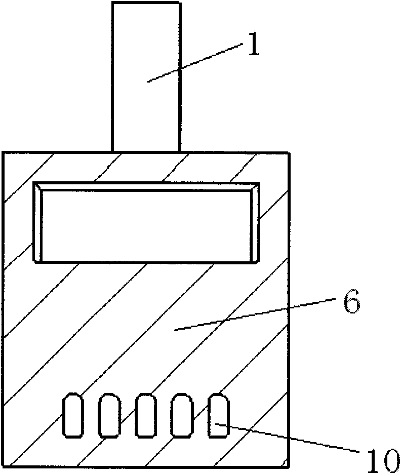
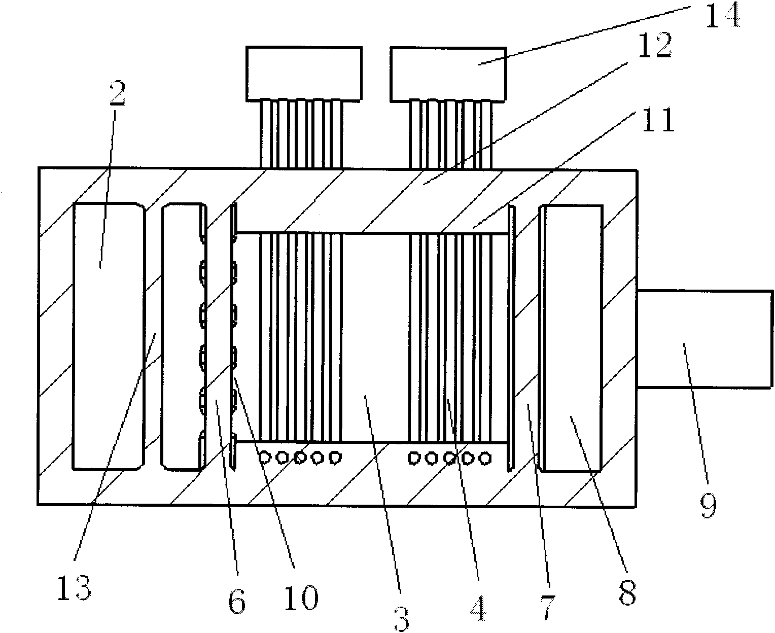
[0015] figure 1 It is the front view of the submerged external heat exchange bed of the circulating fluidized bed. The submerged external heat exchange bed includes a feed riser 1, a feed chamber 2, and a heat exchange chamber 3. The serpentine tube installed in the heat exchange chamber is heated Surface 4, overflow chamber 8, ash return pipe 9, inlet header 14 and outlet header 5. The feeding chamber is divided into two parts by a third partition wall 13 . A first partition wall 6 is arranged between the feed chamber 2 and the heat exchange chamber 3, and a row of underflow holes 10 are set at the bottom of the first partition wall 6 (see figure 2 ), the underflow hole communicates the lower part of the feed chamber 2 with the lower part of the heat exchange chamber 3. The height of the underflow hole 10 is generally 50cm-80cm, the w...


PUM


Abstract

The invention relates to an undercurrent external heat exchanger of a circulating fluidized bed, which comprises a feeding vertical pipe, a feeding chamber, a heat exchanging chamber, a coiled pipe heating surface arranged in the heat exchanging chamber, an inlet header, an outlet header, a first partition wall, a second partition wall, an overflow chamber, an ash returning pipe, and an undercurrent hole; wherein a row of undercurrent holes are arranged at the lower part of the first partition wall between the feeding chamber and the heat exchanging chamber so that both of the upper part and the lower part of the heat exchanging chamber are supplemented by high temperature circulating ash, thus improving the flowing and heat exchanging condition of a dead zone in the heat exchanging chamber; and the upper rand lower temperature gradient of the heating exchanging chamber decreases, which is beneficial to the mixing of the circulating ash; the integral heat exchanging performance of theheat exchanging chamber is enhanced; a walling is arranged next to a side wall; the bend part of the coiled pipe heating surface is buried in the waling, not only bears the support and fixes the coiled pipe and heat exchanger, reduces the vibration of the heat exchanger, but also protects the bend of the heat exchanging surface of the coiled pipe not to be corroded by the circulating ash. The technical solution of the invention is easily realized and beneficial to solve the problems of heat transmission, vibration and abrasion of the external heat exchanger.

Description

technical field [0001] The invention relates to a large circulating fluidized bed boiler, in particular to a circulating fluidized bed boiler with an external heat exchange bed. Background technique [0002] In the process of large-scale circulating fluidized bed boiler, due to the increase of boiler capacity, the ratio of furnace heating surface to volume decreases, it is difficult to balance the arrangement of evaporation heating surface and superheating surface, and it is difficult to control the bed temperature. In the fluidized bed technology, a part of the heating surface in the furnace is moved outside the furnace, and an external heat exchange bed is used. The external bed heat exchanger mainly includes a feed chamber, a heat exchange chamber and an overflow chamber. The serpentine tube heating surface is arranged in the heat exchange chamber. The serpentine tube bundle adopts a suspension structure as a whole, and is connected through the ceiling of the heat exchang...

Claims


Application Information

Patent Timeline
Patent Type & Authority Patents(China)
IPC IPC(8): F22B31/08F23C10/00
Inventor 赵勇王巍郝添翼张建胜杨海瑞吕俊复
Owner TSINGHUA UNIV
Learn More