
Method for designing change pole of rotor in salient pole synchronous generator

A technology of synchronous motor and design method, applied in the direction of single motor speed/torque control, electronic commutation motor control, electrical components, etc., can solve the problem of unequal magnetic pole and small width, low space or material utilization, and complicated rotor winding wiring. and other problems, to achieve the effect of simple switching and high winding utilization.

Active Publication Date: 2010-05-05
HUAZHONG UNIV OF SCI & TECH +1
View PDF0 Cites 8 Cited by
  • Summary
  • Abstract
  • Description
  • Claims
  • Application Information

AI Technical Summary

Problems solved by technology

[0007] The invention provides a design method for changing poles of a salient-pole synchronous motor rotor, which solves the problems of unequal size and width of magnetic poles, complex wiring of rotor windings, and low space or material utilization in existing design methods.

Method used


Image

  • Method for designing change pole of rotor in salient pole synchronous generator
  • Method for designing change pole of rotor in salient pole synchronous generator
  • Method for designing change pole of rotor in salient pole synchronous generator

Examples


Embodiment 1

[0045] One, embodiment 1, comprises the following steps:

[0046] Step 1. Given the number of pole pairs p before the change 1 =12 and the number of pole pairs p after changing 2 =10; select dense groove coefficient k=4;

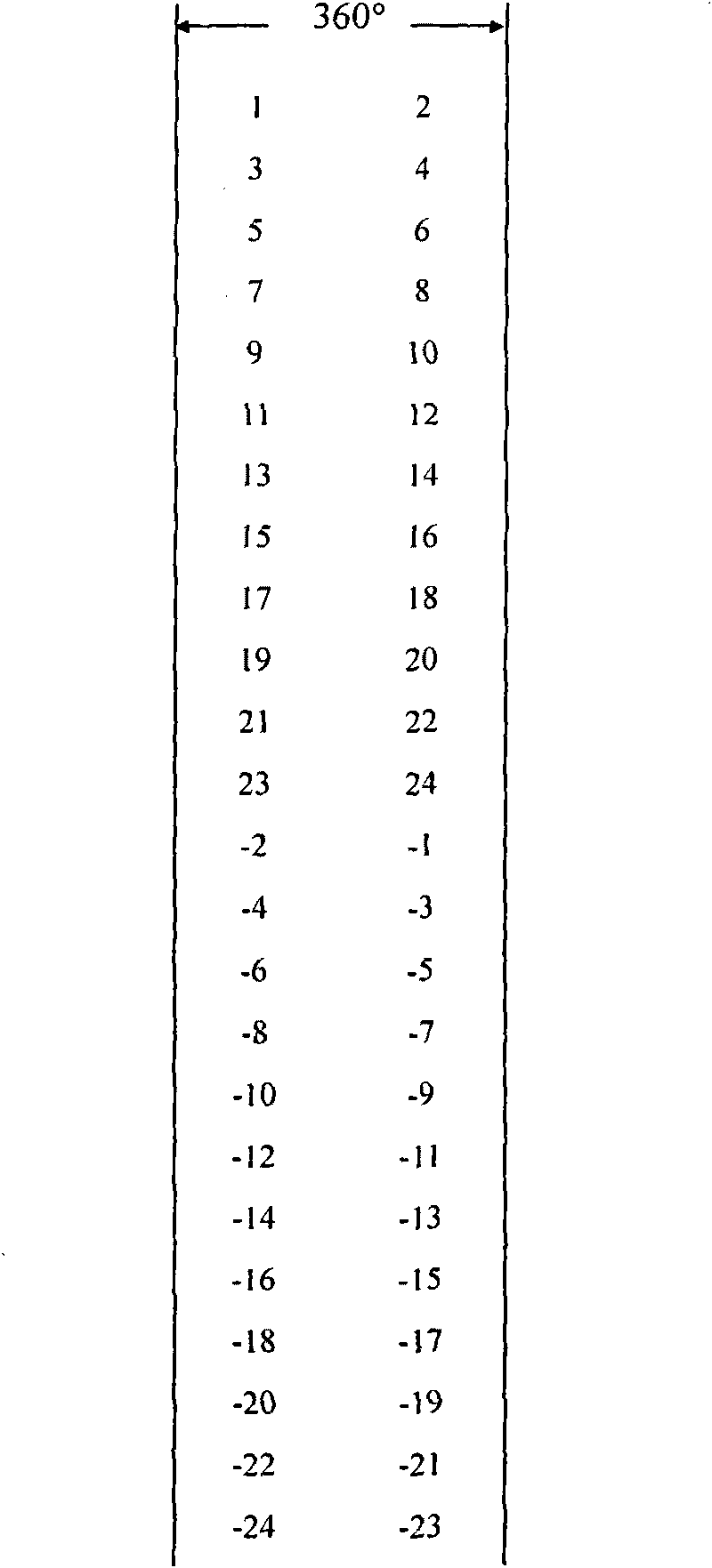
[0047] The second step. Determine the number of virtual rotor slots Z = 2kp 1 =96; according to the given p 1 ,p 2 and Z, respectively as the number of pole pairs before the change p 1 Slot number phase diagram ( image 3 ) and the number of pole pairs p 2 Slot number phase diagram (Fig. 4(a), only draw the 180° range);

[0048] Step 3. The number of pole pairs p before changing 1 Slot number phase diagram ( image 3 ) to select the second column as the original magnetic pole column, and the slot number contained in it represents the initial position of the original magnetic pole before the pole change;

[0049] Step 4. The number of pole pairs p before changing 1 Slot number phase diagram ( image 3 ) respectively select the first column and the...


PUM


Abstract

The invention discloses a method for designing the change pole of a rotor in a salient pole synchronous generator, belonging to a method for designing the structure of the rotor in the salient pole synchronous generator, and solving the problem of the unequal size and width of a magnetic pole; the complex connection of a rotor winding, and low use ratio of material or space. The method comprises the steps of: confirming a pre-change pole pair number P1 and a post-change pole pair number P2, and selecting a dense intensive slot ratio K to ensure a virtual rotor slot number Z; preparing a slot number phase diagram; selecting a primary magnetic pole array and a corresponding movable array, and dividing slot number groups; and replacing an edge slot number of a primary magnetic pole array slot number group with adjoining slot numbers in the movable array to obtain a primary change pole project and carry out harmonic analysis to ensure an official change pole project. The method analyzes a salient pole rotor as a multi-slot non salient pole rotor, removes and selects proper slots therefrom to lead the official change pole project to still have the invariable structure of the salient pole, equalizes the size and the width of the magnetic pole, has high conductor use ratio and low harmonic content, and realizes the three-slip ring switch change pole without needing to abandon any magnetic poles.

Description

technical field [0001] The invention belongs to a rotor structure design method of a salient-pole synchronous motor. Background technique [0002] There are many ways to adjust the speed of synchronous motors, but the pole-changing speed regulation is the most simple and easy. Different from the asynchronous motor, the pole-changing speed regulation of the synchronous motor needs to change the number of pole pairs of the stator winding and the rotor winding at the same time. In principle, the problem of stator winding pole change of synchronous motor is the same as that of asynchronous motor stator winding, and its research has been quite in-depth. The characteristic or difficulty of synchronous motor pole change mainly lies in rotor pole change. [0003] According to different rotor structures, synchronous motors can be divided into hidden pole type and salient pole type. The air gap of the hidden pole machine is uniform and the air gap of the salient pole machine is non-u...

Claims


Application Information

Patent Timeline
Patent Type & Authority Applications(China)
IPC IPC(8): H02P6/00H02P6/08
Inventor 王雪帆朱泽堂
Owner HUAZHONG UNIV OF SCI & TECH
Learn More