
Surgical operation-assisting electrical locking bracket

A technology for locking stents and surgical operations. It is applied in the directions of surgery, surgical robots, and applications. It can solve the problems of not being able to isolate internal organs and lesions well, affecting the doctor's surgical field of vision and operation, and easily fatigued operators. The effect of simple operation, simple structure and easy operation

Inactive Publication Date: 2010-05-12
昆山市工业技术研究院有限责任公司
View PDF0 Cites 18 Cited by
  • Summary
  • Abstract
  • Description
  • Claims
  • Application Information

AI Technical Summary

Benefits of technology

This patented device allows for more flexibility during surgeries than current devices due to its ability to work within three dimensions: tilt (rotation) around one axis), pitch/roll motion or bending at certain angles about another axis. It also includes various features like electrical controls that make it easy to perform operations on both ends without requiring complicated mechanisms such as springs or cables. Additionally, this design uses compressed air instead of traditional hydraulics to achieve balance while still being able to move freely. Overall, these technical improvements improve patient outcomes through improved maneuverability and reduced costs compared to existing systems used today.

Problems solved by technology

This patents discusses how current methods involve manually attaching tools like forceps on patients during medical procedures with significant effort required from operators who must constantly hold them steady throughout their workouts. Additionally, there has been research into developing robots made up entirely of materials instead of handheld ones due to concerns over safety issues such as slipming fingers accidently touch nearby objects causing injury.

Method used


Image

  • Surgical operation-assisting electrical locking bracket
  • Surgical operation-assisting electrical locking bracket
  • Surgical operation-assisting electrical locking bracket

Examples


specific Embodiment approach

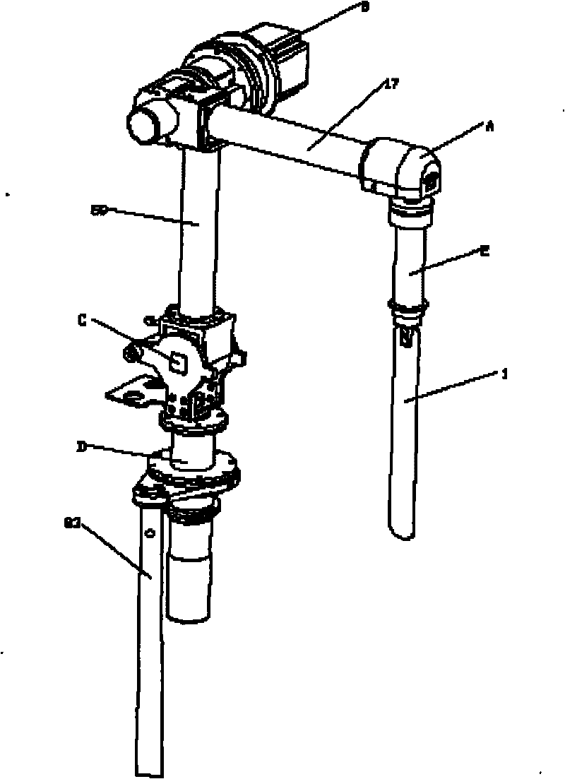
[0059] figure 1 It is a schematic diagram of the overall structure of an embodiment of the present invention.

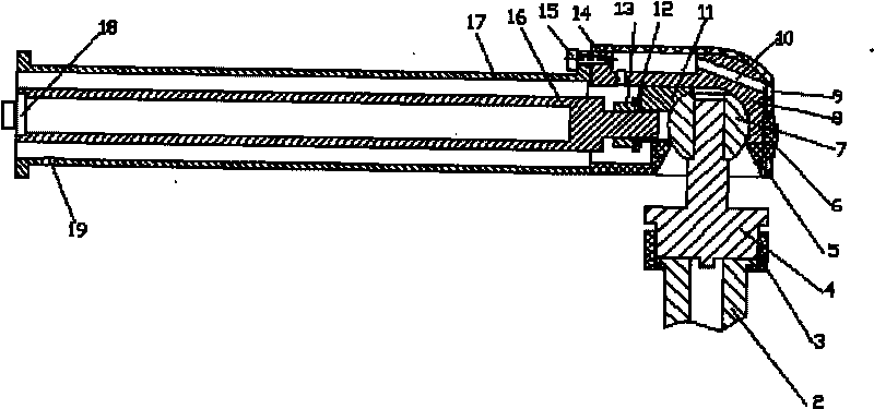
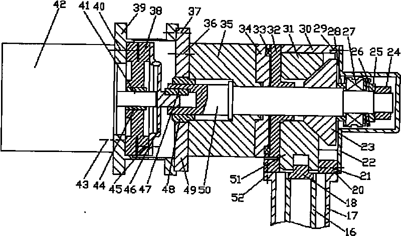
[0060] like figure 1 Shown: an electric locking bracket for assisting surgical operations, including a handle 2, a wrist joint A, a forearm 17, an elbow joint B, a large arm 59, a shoulder joint C, a waist joint D and a base rod 83, wherein, One end of the handle 2 is connected with the surgical auxiliary tool 1, and the other end is connected with the wrist joint A, and the wrist joint A is also connected with one end of the forearm 17, while the other end of the forearm 17 is connected with the elbow joint B, and the elbow joint B At the same time, it is connected to one end of the big arm 59, while the other end of the big arm 59 is connected to the shoulder joint C, which is also connected to the waist joint D at the same time, and the joint axes of the shoulder joint C and the waist joint D are perpendicular to each other. In addition, The lumbar joint D is al...


PUM


Abstract

The invention discloses a surgical operation-assisting electrical locking bracket, which comprises a handle, a wrist joint, a fore arm, an elbow joint, an upper arm, a shoulder joint, a waist joint and a base rod, wherein one end of the handle is connected with an operation-assisting tool; the other end of the handle is connected with the wrist joint connected with one end of the fore arm; the other end of the fore arm is connected with the elbow joint connected with one end of the upper arm; the other end of the upper arm is connected with the shoulder joint connected with the waist joint; the joint axes of the shoulder joint and the waist joint are perpendicular to each other; and the waist joint is connected with the base rod through a machine frame arranged on the waist joint. The bracket has four joints, six degrees of freedom, position and attitude decoupling and large tail-end working space and can meet needs of surgical departments such as thoracoabdominal department. In addition, the bracket has the advantages that: the operation is very convenient; the structure is simple; the cost is low; and a weight self-balancing mechanism can perform adjustment according to the load at a tail end.

Description


Claims


Application Information

Patent Timeline
Owner 昆山市工业技术研究院有限责任公司
Learn More