Direct-drive motor heat sink of industrial sewing machine

A technology for industrial sewing machines and direct-drive motors, which is applied to sewing machine control devices, sewing machine components, sewing equipment, etc., can solve the problems of lack of heat dissipation, bulky, and unsatisfactory use design, and achieve the effect of ensuring service life.

Inactive Publication Date: 2010-05-12
顾飞龙
View PDF0 Cites 9 Cited by
  • Summary
  • Abstract
  • Description
  • Claims
  • Application Information

AI Technical Summary

Problems solved by technology

It can be seen from the drawings that the sewing machine needs to be molded and custom-formed to form a housing space that can accommodate the servo motor. Therefore, the cost is high and the volume is large, so a heat dissipation structure is required to help the servo motor dissipate heat, and this type of design The model has a unique built-in transmission structure, which cannot be used with other types of accessories; therefore, the use design is not ideal
[0003] In addition, recently, some operators have launched a direct-drive sewing machine, which is a type of sewing machine head equipped with a direct-drive motor to replace the traditional belt drive when it leaves the factory. However, this direct-drive sewing machine does not have heat dissipation Instead, the heat generated by the direct drive motor is directly blown by the industrial fan in the working workshop, but this method cannot achieve comprehensive heat dissipation of the motor, and only the side blown by the fan has the effect of cooling and heat dissipation , so the heat dissipation efficiency is still not ideal

Method used


Image

  • Direct-drive motor heat sink of industrial sewing machine
  • Direct-drive motor heat sink of industrial sewing machine
  • Direct-drive motor heat sink of industrial sewing machine

Examples


Embodiment 1

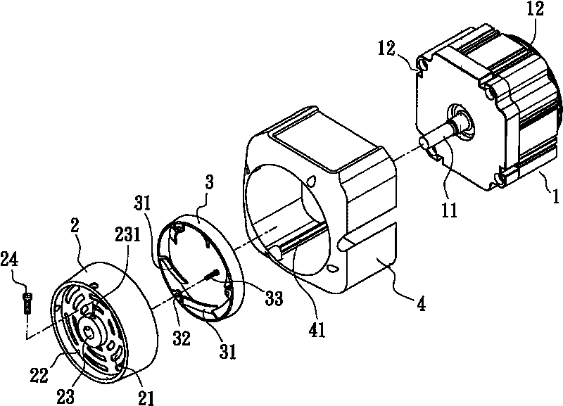
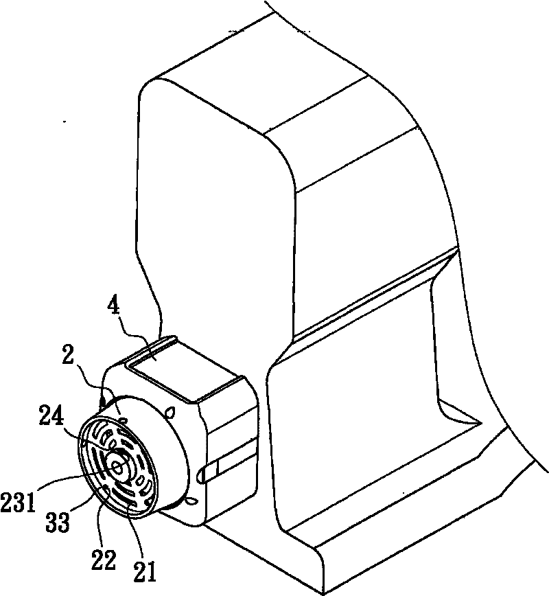
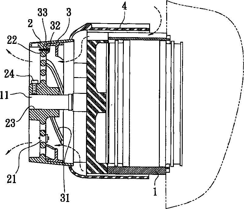
[0021] First, see Figure 1 ~ Figure 3 As shown, it is a three-dimensional disassembly, combination and combined sectional schematic diagram of Embodiment 1 of the direct drive motor cooling device of the industrial sewing machine of the present invention. Wheel 2, the center of the hand wheel 2 is provided with a through hole 23 which is nested with the main shaft 11, the periphery of the through hole 23 has a threaded hole 231 for a threaded part 24 to be screwed, and the side of the hand wheel 2 is provided with multiple exhaust Holes 21 and screw holes 22 are provided, and a heat dissipation fan 3 with guide vanes 31 is assembled correspondingly from the inside of the handwheel 2, and the screw hole 22 of the handwheel 2 corresponds to the inner surface of the heat dissipation fan 3. The perforated holes 32 are connected together by screws 33, and a shell 4 is set outside the direct drive motor 1 to connect to the hand wheel 2. The inside of the shell 4 is provided with a ...

Embodiment 2

[0024] see Figure 5 As shown, it is a schematic diagram of another embodiment of the direct-drive motor cooling device of the industrial sewing machine of the present invention. The difference from Embodiment 1 is that the direction of the deflector 31 of the cooling fan 3 is corresponding to when the direct-drive motor 1 is running. It can be designed to generate deflections. Therefore, when the main shaft 11 of the direct drive motor 1 is rotating, there are left and right rotations respectively, and the deflectors 31 of the cooling fan 3 are like figure 1 and Figure 5 The direction of the deflector 31 of the cooling fan 3 is different to correspond to the direct drive motor 1, and the hole 32 is used to correspond to the screw hole 22 of the hand wheel 2, and the screws 33 are assembled together to achieve Exhaust cooling effect.


PUM


Abstract

The invention relates to a direct-drive motor heat sink of an industrial sewing machine, wherein a hand wheel is assembled correspondingly at the back end of a main shaft of a direct-drive motor for supplying power to a sewing machine stand, a radiator fan is assembled at a part corresponding to the direct-drive motor in the interior of the hand wheel, and an outer shell is sleeved at the outside of the direct-drive motor to the hand wheel to form a diversion channel. Compared with the prior art, the invention disperses the high temperature generated by the operation of the direct-drive motor by the radiator fan through vents of the hand wheel, simultaneously ensures the diversion channel to form a cross-ventilated pipeline so as to realize the excellent heat radiating effect and ensure the service life of the direct-drive motor.

Description

technical field [0001] The invention relates to a heat dissipation device for a direct drive motor of an industrial sewing machine. Background technique [0002] The heat dissipation structure of a general traditional sewing machine is roughly as the heat dissipation structure of a sewing machine built-in drive disclosed in Taiwan Announcement No. M334869. Its specific structure includes: a servo motor that drives the sewing machine is fixed on the top of a housing, The servo motor has a transmission shaft, and one end of the servo motor is provided with a radiator driven by the transmission shaft and placed in the casing, and at least one first pair of The circulation hole and at least one second pair of circulation holes. It can be seen from the drawings that the sewing machine needs to be molded and custom-formed to form a housing space that can accommodate the servo motor. Therefore, the cost is high and the volume is large, so a heat dissipation structure is required t...

Claims


Application Information

Patent Timeline
Patent Type & Authority Applications(China)
IPC IPC(8): D05B71/00D05B69/10
Inventor 顾飞龙
Owner 顾飞龙
Why Eureka
Try Eureka