Flapping wing lift generating device

A technology for generating device and lift force, applied in the field of flapping wing aircraft, can solve problems such as flapping range restriction, and achieve the effect of large lift force and high efficiency

Inactive Publication Date: 2010-05-19
HARBIN ENG UNIV
View PDF1 Cites 65 Cited by
  • Summary
  • Abstract
  • Description
  • Claims
  • Application Information

AI Technical Summary

Problems solved by technology

"Its disadvantages are: the wingspan and the flapping range to generate lift a

Method used


Image

  • Flapping wing lift generating device
  • Flapping wing lift generating device
  • Flapping wing lift generating device

Examples


Embodiment Construction

[0019] The present invention is described in more detail below in conjunction with accompanying drawing example:

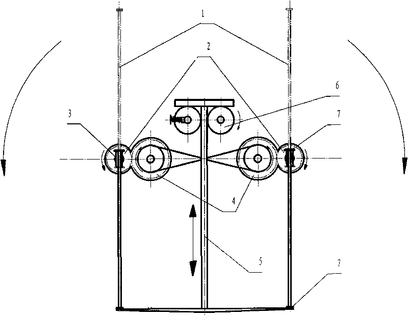
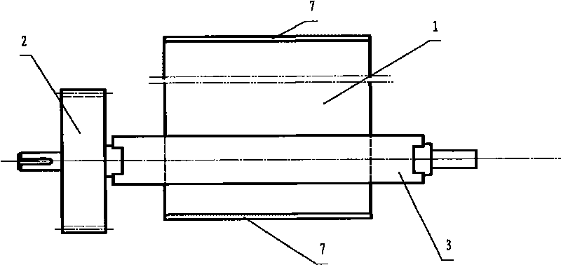
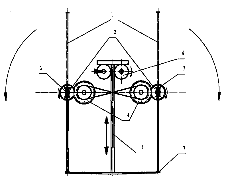
[0020] to combine figure 1 As shown, a flapping wing lift generating device is to fix two sets of assemblies with the same structure axisymmetrically together, and each set of assemblies includes a flapping wing piece 1, a baffle plate 7, a flapping gear 2, and a flapping shaft 3 , drive gear 4, lifting rod 5 and lifting wheel 6; wherein, the flapping wing 1 is a rigid rectangular plate with a baffle 7 at the end; the flapping shaft 3 is clamped by two flapping flaps 1 and allows flapping The strip splint in which the fin 1 slides and two sections of the coaxial shaft head at the end are composed of a flapping gear 2 fixed on the shaft head at one end (see figure 2 ); the upper and lower limit positions of the flapping wing 1 sliding in the strip splint are respectively located in the vertical plane, and are formed by the baffle plate 7 abutting against the edg...


PUM


Abstract

The invention provides a flapping wing lift generating device, comprising a flapping wing mechanism, a flapping wing rotating mechanism and a flapping wing lifting mechanism, which are installed on an ornithopter. The flapping wing mechanism comprises two flapping wing blades and two flapping axles. Each flapping wing blade is a rigid rectangular plate with baffles at the ends. Each flapping axle is composed of two strip splints which clamp the flapping wing blades and allow the flapping wing blades to glide in the strip splints and two sections of coaxial axle heads positioned at the ends of the strip splints. The flapping wing rotating mechanism comprises a flapping gear fixed on an axle head at one end of the flapping axle, driving gears meshed with the flapping gear, a driving belt or a driving chain between the two driving gears. One driving gear is connected with a rotating motor. The flapping wing lifting mechanism comprises a lifting rod and lifting wheels. The lifting rod is an I-shaped member. The two lifting wheels clamp the web rod of the I-shaped member. One lifting wheel is driven by a lifting motor. The device has high efficiency and large lift and can be used as the propeller of air or water transportation.

Description

technical field [0001] A flapping-wing lift generating device belongs to the field of flapping-wing aircraft. Background technique [0002] Human beings long to imitate birds to fly alone and freely in the sky, but they have realized their own flying desires in a different way—all effective flying machines do not have flapping wings (flapping wings) like birds, but Developed based on the constantly improving "wing theory". The history of human research on "bionic flight" is full of hardships and failures, and some people assert that it is impossible for human beings to fly with the help of flapping wings. Despite this, modern people who have overcome various technological difficulties are still unwilling to give up "bionic flight". In their view, only the flight of birds is personalized, and it does not need modern airports, long and solid runways, and huge logistical support. When you use "ornithopter" and "ornithopter" to search Chinese and foreign patent databases, a l...

Claims


Application Information

Patent Timeline
IPC IPC(8): B64C33/02A63H27/28
Inventor 李鸿郑全逸
Owner HARBIN ENG UNIV
Why Eureka
Try Eureka