Quick joint

A fast and connecting hole technology, which is applied in the direction of pipe/pipe joint/pipe fitting, sealing surface connection, passing components, etc., can solve the problems of reducing the qualified rate, increasing the difficulty of processing, and scrapping the joint, so as to achieve convenient snap-in mechanism or sealing circle, low production requirements, and easy maintenance and replacement

Inactive Publication Date: 2010-05-19
玉环县林波铜业制品厂
View PDF1 Cites 6 Cited by
  • Summary
  • Abstract
  • Description
  • Claims
  • Application Information

AI Technical Summary

Problems solved by technology

[0004] Although the above-mentioned structure has achieved the problem of fast and convenient installation and disassembly, it also has the following defects: First, the riveting process forms a wrapping edge that resists the shoulder on the positioning mechanism by pressing the end of the connecting piece inward, so that the positioning mechanism is axially fixed
The existing riveting process of this structure can easily cause uneven riveting by pressing the edge of the end, and if it is not well mastered, it is easy to press and damage the positioning mechanism protruding in the middle and the port of the connecting piece to press out cracks, causing the joint to be scrapped, reducing the qualified rate, and increasing manufacturing costs. The second is that after the quick connection structure of the pipe is finished, the body and the connecting piece are integrated. Since the riveting process is used to form the wrapping edge to resist the shoulder to fix the positioning mechanism, the positioning mechanism is stuck in the cavity of the connecting piece and cannot be taken out. The middle fixing mechanism or collar is damaged and cannot be repaired, so that the entire joint is scrapped, resulting in defects such as short life and waste of materials; the third is to use riveting technology to fix the positioning mechanism at the end of the connector, and special riveting equipment must be used to increase Processing difficulty, increase cost

Method used


Image

  • Quick joint
  • Quick joint
  • Quick joint

Examples


Embodiment 1

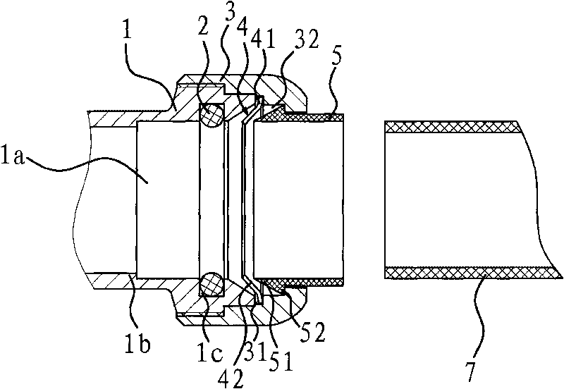
[0028] Such as figure 1 As shown, the quick connector includes a body 1 , a sealing ring 2 , a clamping mechanism, and a fixing cap 3 .

[0029] Specifically, the body 1 is cylindrical and has a connection hole 1a, and an annular bead 1b is provided on the inner wall of the connection hole 1a, and the end face of the connecting pipe 7 inserted into the connection hole 1a can abut against the end face of the ring bead 1b, thereby Prevent the connecting pipe 7 from being inserted into the body 1 too much. There is also an annular groove 1c on the inner wall of the connection hole 1a, and the annular groove 1c is located on the outside of the annular bead 1b, and the sealing ring 2 is fixed in the annular groove 1c, and the sealing ring 2 can circumferentially seal the socket inserted into the connecting hole. Take over 7.

[0030] The fixed cap 3 is cylindrical and one end is fixed on the body 1 and the clamping mechanism is fixed at the entrance of the connection hole 1a (the...

Embodiment 2

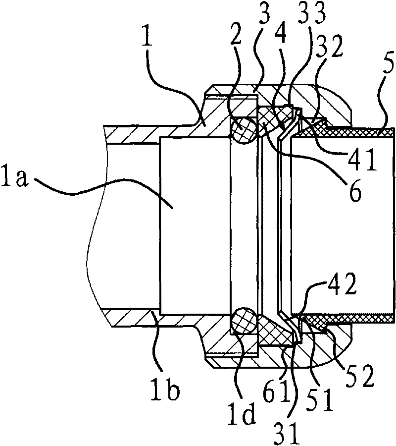
[0035] The structure and principle of this embodiment are basically the same as that of Embodiment 1, the difference is that: figure 2 As shown, the entrance of the connecting hole 1a is provided with an annular concave shoulder 1d, and the sealing ring 2 is embedded on the annular concave shoulder 1d. There is an annular ferrule pad 6 inside the annular step 1, one end of the ferrule pad 6 is against the ring frame 41 of the collar 4, and the other end is against the end surface of the body 1 and the end is pressed and sealed at the same time Ring 2, so that the sealing ring 2 is fixed on the annular concave shoulder 1d. The inner edge of the abutting surface of the ferrule pad 6 and the collar 4 has a conical installation portion for installing the claw 42 and allowing the claw 42 to have a space to expand.

[0036] An annular positioning groove 33 is formed on the side wall of the annular step one 31, and a positioning ring 61 is provided on the outer wall of the ferrule ...

Embodiment 3

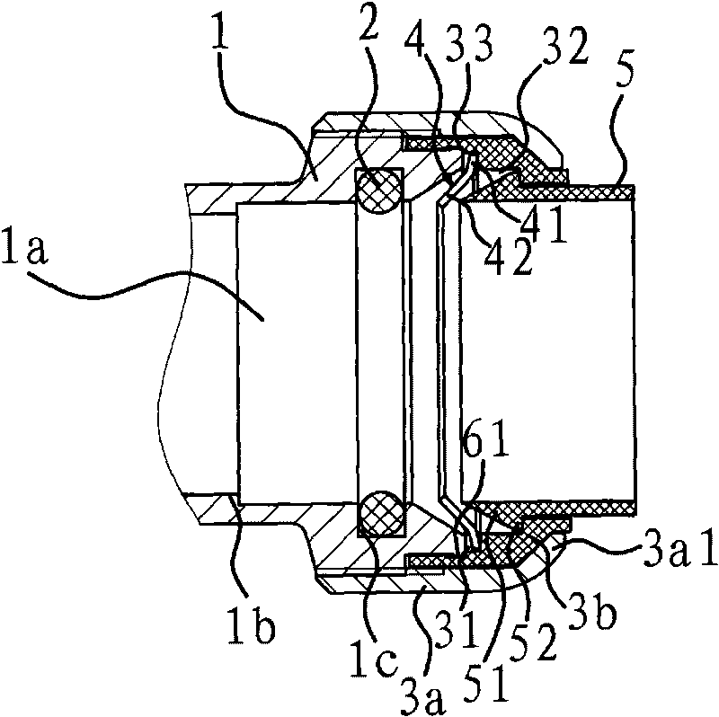
[0038] The structure and principle of this embodiment are basically the same as that of Embodiment 1, the difference is that: image 3As shown, the fixed cap 3 includes a cap body 1 3a fixedly connected to the body 1 and a cap body 2 3b located in the cap body 1 3a, and the above-mentioned annular step 1 31 and annular step 2 32 are all located on the inner wall of the cap body 2 3b . The outer end surface of the first cap 3a has a rim 3a1 facing the axis, and the outer end of the second cap 3b presses against the rim 3a1 of the first cap 3a. Annular positioning groove 33 is opened on the side wall of annular step one 31, and positioning ring 61 is arranged on the outer wall of main body 1, and this positioning ring 61 is embedded in the positioning groove, and cap body 3b is preliminarily fixed on the main body 1, and cap body one 3a It is fixed on the main body 1 by threaded connection or welding so that the cap body 2 3b is fixed more firmly. The second cap body 3b is mad...


PUM


Abstract

The invention provides a quick joint belonging to the technical field of pipeline connection and solving the problems of low qualification rate, incapable maintenance, short service life and high cost of the traditional quick joint. The quick joint is provided with a body with a connecting hole which is internally provided with a sealing ring capable of forming the seal with an inserted connecting pipe; and a clamping mechanism capable of clamping or releasing the inserted connecting pipe is arranged at a port of the connecting hole and can be fixed on the body by a fixed cap. The fixed cap is fixedly connected to the body by welding or adopting threads. The quick joint has the advantages of convenient processing, low condition required by the production, convenient and firm connection and convenient maintenance and replacement of the clamping mechanism or the sealing ring.

Description

technical field [0001] The invention belongs to the technical field of pipeline connection, and relates to a joint, in particular to a quick joint. Background technique [0002] A pipeline is a device used to transport gas, liquid or fluid with solid particles connected by pipes, pipe connectors and valves. At present, in various pipeline connections, in order to facilitate the arrangement and installation of pipes, conduit joints are often used to realize steering and connection. According to the form, such as bend, straight, tee, etc., each channel can be made into equal or different lengths. path. Existing joint connection methods include welding type, clamping type, threaded type, etc., which are generally simple structures as existing joints. In actual application, the existing joints have problems such as inconvenient manufacture and installation, difficult loading and unloading, and slow speed. [0003] In order to solve the above-mentioned problem, people have inv...

Claims


Application Information

Patent Timeline
IPC IPC(8): F16L37/08F16L37/10F16L19/03
Inventor 王辉春
Owner 玉环县林波铜业制品厂
Why Eureka
Try Eureka