Stainless steel molding rod, manufacturing method and application thereof

A technology of stainless steel rods and stainless steel, which is applied in the field of quartz crucible manufacturing, can solve the problems of fragile quartz glass forming rods, poor precision, and misunderstanding of thinking, and achieve the effect of rich raw materials, high precision, and improved quality

Inactive Publication Date: 2012-07-04
余姚市启明石英有限公司
View PDF0 Cites 0 Cited by
  • Summary
  • Abstract
  • Description
  • Claims
  • Application Information

AI Technical Summary

Problems solved by technology

[0007] One purpose of the present invention is to solve the above-mentioned problems in the prior art that the quartz glass molding rod is fragile, poor in accuracy, and unable to be adjusted during use, and there is a thinking in the prior art that only high-purity materials can be used to make the molding rod Misunderstandings and other problems, provide a durable, high-precision, easy-to-adjust stainless steel forming rod

Method used


Image

  • Stainless steel molding rod, manufacturing method and application thereof
  • Stainless steel molding rod, manufacturing method and application thereof
  • Stainless steel molding rod, manufacturing method and application thereof

Examples


Embodiment 1

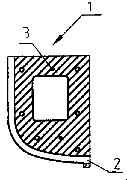
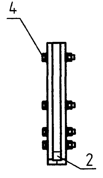
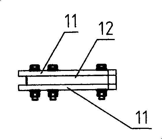
[0048] As shown in Figure 1 (A), (B) and (C), a crucible stainless steel forming rod template includes a splint 1, and also includes an end clamp hole 2, a positioning pin 3, a fastening bolt 4, and a template The working surface is on the left and lower sides of splint 1. The working surface is composed of a straight line and two arcs. The left side is a straight line, the lower side is an R1 arc segment, and the lower left side is an R2 arc segment. The shape of the working face is consistent with the shape of the stainless steel forming rod; the splint 1 is divided into three layers, the two side splints 11 and the center splint 12, and the working surface formed by the two side splints 11 and the center splint 12 is concave; the three-layer splint is used Locating pin 3 locates, connects with fastening bolt 4.

[0049] The end clamp hole 2 is located at the lower right of the former, the upper half of the end clamp hole 2 is the concave working surface of the former, and the...

Embodiment 2

[0052] A stainless steel forming rod 9, comprising a rod body 5 and a positioning pointer 6; the upper part of the rod body is a stainless steel straight rod structure 5.1, and the lower part is a curved stainless steel rod structure 5.2. The bending has two arcs, one of which is R1, one section is R2; the tail end is adjustable positioning pin 6.

[0053] R1 radius is 80mm, R2 radius is 503mm.

[0054] The adjustable positioning needle 6 includes a needle body 6.1 and an adjustment screw 6.2; the top of the needle body has an adjustment groove, the middle part is a threaded structure, and the lower part is a cone-shaped structure; the middle part of the needle body is connected to the threaded structure of the adjustment screw thread 6.2 .

[0055] The tail end of the stainless steel formed rod body is fixedly connected to the adjustment screw part of the adjustable positioning pin, and the fixed connection is welding.

Embodiment 3

[0057] The quartz sand layer 7 is placed in the mold 8, and under the action of centrifugal force, the crucible product can be obtained by using a stainless steel forming rod 9 and forming it at a high temperature.


PUM

PropertyMeasurementUnit
diameteraaaaaaaaaa
thicknessaaaaaaaaaa

Abstract

The invention relates to the field of manufacturing quartz crucibles, in particular to a stainless steel molding rod, a manufacturing method and application thereof. The invention solves the problem that quartz glass molding rods in the field of the prior art are fragile, poor in precise, incapable of adjustment in use and the like, as well as the problem that a mistaken thought that only high-purity materials can be used to manufacture molding rods exists in the prior field. The invention provides the stainless steel molding rod, which comprises a rod body and a positioning pointer, wherein the upper part of the rod body has a stainless-steel straight-rod structure; the lower part of the rod body has a bent stainless-steel rod-like structure; a bend has two segments of radian; one segment is R1, and the other segment is R2; and the tail end of the rod is an adjustable positioning pointer. The rod has the advantages of sturdiness, durability, high precision and adjustment convenience.

Description

technical field [0001] The invention relates to the field of quartz crucible manufacture, and relates to a stainless steel forming rod, a manufacturing method thereof and an application of the forming rod. Background technique [0002] All domestic enterprises that manufacture quartz crucibles by arc method must use forming tools-forming rods when the quartz sand is formed in the mold by centrifugal force. Traditional forming rods are made of quartz glass rods, but there are many defects in the use of quartz glass forming rods. [0003] 1. Since the quartz glass molding rod is a fragile material, it will break if it is accidentally bumped during use, especially the positioning pin is very easy to break. [0004] 2. It is difficult to manufacture, and at the same time, the precision is not high. Because the temperature of the deformation point of quartz glass is very high, it must be processed by a professional manufacturer with a hydrogen-oxygen combustion flame. Because it...

Claims


Application Information

Patent Timeline
Patent Type & Authority Patents(China)
IPC IPC(8): C03B20/00C30B15/10
CPCC03B19/095
Inventor 黄乃军黄洁
Owner 余姚市启明石英有限公司
Why Eureka
Try Eureka