Eureka AIR delivers breakthrough ideas for toughest innovation challenges, trusted by R&D personnel around the world.

Film plating device

A technology of coating device and evaporation source, which is applied in the direction of sputtering coating, ion implantation coating, vacuum evaporation coating, etc., can solve the problems of time-consuming, inconsistent film characteristics, prolonging the coating processing time, etc., and shorten the coating process time, the effect of reducing the number of times of heating and vacuuming

Inactive Publication Date: 2012-10-10
HONG FU JIN PRECISION IND (SHENZHEN) CO LTD +1
View PDF0 Cites 0 Cited by
  • Summary
  • Abstract
  • Description
  • Claims
  • Application Information

AI Technical Summary

Problems solved by technology

However, in the existing vacuum coating equipment, only one side of the product can be coated at a time. If the product needs to be coated on both sides, the vacuum chamber must be opened, and the bearing part carrying the product must be manually turned over.
This will have the following disadvantages: first, two vacuum pumping operations are required, which is time-consuming; second, the temperature in the vacuum chamber is extremely high during evaporation, so when turning over manually, you must wait until the vacuum chamber cools down. Open the vacuum chamber, take out the carrying part, turn it over and put it into the vacuum chamber, which prolongs the processing time of the coating; thirdly, the vacuum chamber needs to be opened twice, and the environmental parameters in the vacuum chamber cannot be kept completely consistent. This leads to inconsistencies in the characteristics of the film layers on both sides of the product; fourth, when the vacuum chamber is opened, the cleanliness of the product will decrease, which will affect the product yield

Method used


Image

  • Film plating device
  • Film plating device
  • Film plating device

Examples


Embodiment Construction

[0011] The present invention will be further described in detail below in conjunction with the accompanying drawings.

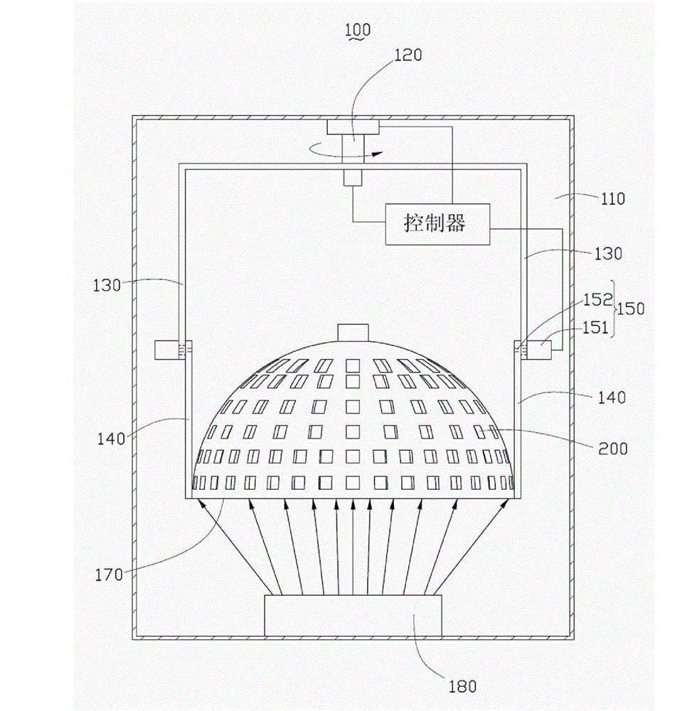
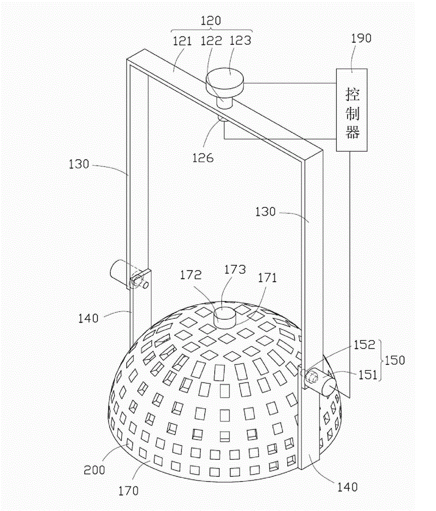
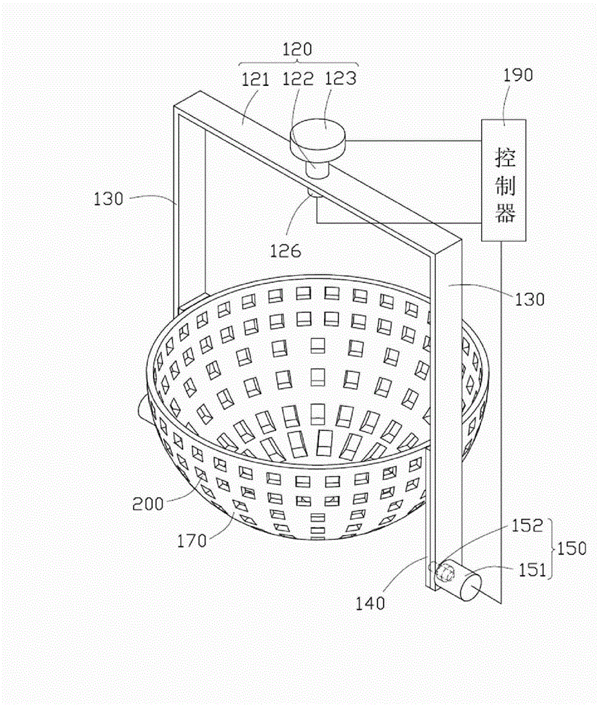
[0012] see figure 1 and figure 2 , is a coating device 100 provided in the first embodiment of the present invention, and is used for coating a product 200 . The coating device 100 includes a vacuum chamber 110, a rotating support assembly 120, two fixed arms 130, two overturning arms 140, two overturning motors 150, a carrier 170, an evaporation source 180, and a controller 190.

[0013] The rotating support assembly 120 includes a supporting frame 121, a rotating shaft 122 and a rotating motor 123, the rotating motor 123 is fixed on the top of the vacuum chamber 110, and the supporting frame 121 is connected to the rotating shaft 122. One end, the other end of the rotating shaft 122 is connected with the rotating motor 123 , so that the supporting frame 121 can rotate in the horizontal plane driven by the rotating motor 123 . An infrared receiver 126 i...


PUM


Abstract

The invention relates to a film plating device which comprises a vacuum cavity, a rotary support assembly, two fixing arms, two turning motors, a bearing part, a vapor deposition source and a controller, wherein the rotary support assembly is provided with an infrared receiver; the two fixing arms are respectively fixed on the rotary support assembly; the bearing part is provided with an infraredtransmitter; the vapor deposition source is arranged at the bottom of the vacuum cavity; the controller can be electrically connected with the two turning motors and the infrared receiver at the sametime; the rotary support assembly can be rotatably fixed at the top of the vacuum cavity; the bearing part can be rotatably connected with the two fixing arms; and the turning motors are fixed on thefixing arms, and are fixedly connected with the bearing part. For the film plating device, the turning motors are utilized to enable the bearing part to automatically turn, and the infrared receiver and the infrared transmitter on the rotary support assembly and the bearing part are utilized, and the controller which is electrically connected with the infrared receiver is combined to realize the positioning of the bearing part after turning, thereby both sides of the product can be plated with films without opening the vacuum cavity.

Description

technical field [0001] The invention relates to a coating device. Background technique [0002] In order to make the film on the surface of the product more pure, the coating process must be completed in a vacuum environment, that is, vacuum coating. The main process of vacuum coating is to place the cleaned product on the carrier, send the carrier into the vacuum chamber of the coating machine, heat and pump the vacuum chamber to reach the vacuum range required for the coating process, and then The evaporation source is heated to make the coating material into an ionic state, and then the ionic coating material evaporates to reach the surface of the product, and gradually deposits on the surface of the product to form a thin film. The evaporation time varies depending on the number of film layers and procedures to be deposited. After the coating is completed, the bearing part is taken out after the vacuum chamber is cooled. [0003] At present, as the optical properties ...

Claims


Application Information

Patent Timeline
Patent Type & Authority Patents(China)
IPC IPC(8): C23C14/24
Inventor 王仲培
Owner HONG FU JIN PRECISION IND (SHENZHEN) CO LTD
Why Eureka
Eureka Blog
Learn More