
Display device

A display device and technology for display, applied to static indicators, standard conversion, instruments, etc., can solve problems such as dynamic image blur and edge partial blur, and achieve the effect of suppressing the increase of circuits

Active Publication Date: 2010-05-26
JAPAN DISPLAY INC +1
View PDF3 Cites 6 Cited by
  • Summary
  • Abstract
  • Description
  • Claims
  • Application Information

AI Technical Summary

Problems solved by technology

As a disadvantage of the hold-type display device, when displaying a moving image, the edge portion of a moving object looks blurred, so-called moving image blur

Method used


Image

  • Display device
  • Display device
  • Display device

Examples


Embodiment approach 1

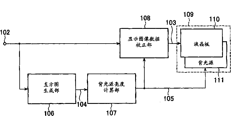
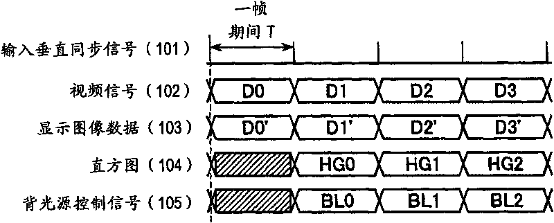
[0026] Figure 3A It is a diagram for explaining a schematic configuration of a liquid crystal display device as an example of the display device according to Embodiment 1 of the present invention. especially, Figure 3A Is a block diagram for explaining the schematic configuration of the liquid crystal display device according to the first embodiment of the present invention, Figure 3B It is an operation diagram for explaining the operation of the liquid crystal display device according to Embodiment 1 of the present invention. Figure 3A The liquid crystal display device of the first embodiment shown is a liquid crystal display device having an interpolation frame interpolation method and a backlight brightness modulation method. However, in this specification, N is 0 and a natural number.

[0027] Such as Figure 3A As shown, the liquid crystal display device of the first embodiment of the present invention includes a frame rate conversion storage unit 306, an interpolation fr...

Embodiment approach 2

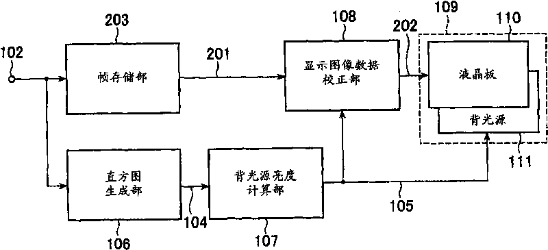
[0049] Figure 4A It is a figure for demonstrating the schematic structure of the liquid crystal display device which is an example of the display device of Embodiment 2 of this invention. especially, Figure 4A It is a block diagram for explaining the schematic configuration of a liquid crystal display device according to Embodiment 2 of the present invention, Figure 4B It is an operation diagram for explaining the operation of the liquid crystal display device according to Embodiment 2 of the present invention. Figure 4A The liquid crystal display device of Embodiment 2 shown is a liquid crystal display device having a bright and dark field division method and a backlight brightness modulation method.

[0050] Such as Figure 4A As shown, the liquid crystal display device according to the second embodiment of the present invention includes a frame rate conversion storage unit 406, a bright and dark field generation unit 407, a display image data correction unit 408, a histogra...


PUM


Abstract

The display device including: a display panel; a backlight; a memory for converting frame rate of an input video signal and outputting a video signal; an interpolation frame generation unit for generating an interpolation frame based on the video signal output from the memory; a histogram generator for generating a histogram based on the input video signal; and a backlight brightness calculation unit for calculating a backlight control signal, the display device further comprising: wherein image data for display, which is obtained by an N-th frame of the input video signal, and image data of the interpolation frame generated based on the N-th frame and an (N+1)-th frame of the input video signal, is input to the display panel; and wherein the backlight control signal calculated based on the histogram generated based on the image data of the N-th frame is used for displaying the image data for display.

Description

Technical field [0001] The invention relates to a display device and a driving method thereof. More specifically, it relates to a display device that performs display by linking a video signal and light source brightness control when controlling the brightness of a light source based on a video signal. Background technique [0002] In recent years, non-luminous display devices represented by liquid crystal display devices have become widespread. The non-luminous display device uses a light source and a light modulation element that adjusts the amount of light transmitted from the light source. In a non-luminous display device, the power consumption of the light source and the reduction in contrast caused by light leakage from the light source during black display become a problem. To this end, in order to improve power consumption and contrast, a variety of methods for controlling the brightness of the light source by video signals have been proposed. As an example, Japanese P...

Claims


Application Information

Patent Timeline
Patent Type & Authority Applications(China)
IPC IPC(8): G09G3/34G09G3/36
CPCG09G3/2025G09G3/3406G09G2360/16G09G3/2081G09G3/2011G09G3/3611G09G2340/0435H04N7/0132G09G2320/0646G09G2320/0261G09G2320/0271
Inventor 大石纯久丸山纯一庄司孝志小野记久雄深田齐仙
Owner JAPAN DISPLAY INC
Learn More