
Dispensable continuous negative-pressure puncture outfit

A disposable trocar technology, applied in the direction of suction instruments, trocars, etc., can solve the problems of low accuracy of fine needle aspiration cytopathology, bulky trocar feel, and backward use level, etc., to achieve simple structure and lighten the patient Painful, concentrated effort ensures the effect

Active Publication Date: 2010-06-02
余小蒙
View PDF0 Cites 10 Cited by
  • Summary
  • Abstract
  • Description
  • Claims
  • Application Information

AI Technical Summary

Benefits of technology

This innovation makes precise sampling easier for medical professionals while reducing their risk of injury from sharp instruments used during biopsy procedures. Its technical effect lies within its simplicity and ease of use compared with existing methods like syringes or other tools commonly found outside hospitals.

Problems solved by technology

This patented technical problem addressed in the current practice of collecting samples through manual methods involves errors caused during the process that can make precise analysis difficult or impossible with existing devices used at homecare facilities like histoplasmectomy surgery (Hoover).

Method used


Image

  • Dispensable continuous negative-pressure puncture outfit
  • Dispensable continuous negative-pressure puncture outfit
  • Dispensable continuous negative-pressure puncture outfit

Examples


Embodiment 1

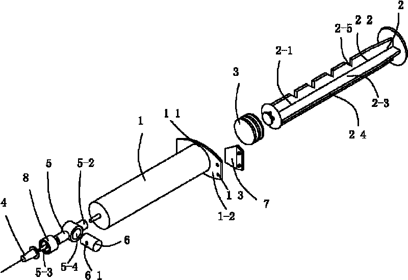
[0032] Disposable continuous negative pressure trocar embodiment, see figure 1 , the continuous negative pressure puncturer includes a needle tube 1, a needle plug 2 and a piston 3 in the needle tube, one end 2-1 of the needle plug is connected with the piston inside the needle tube, and the other end 2-2 is outside the needle tube, and is manually Pushing the needle pin back and forth drives the piston to move back and forth in the needle tube, a puncture needle 4 is arranged at the front end of the needle tube, and a stopper device is arranged between the puncture needle and the needle tube;

[0033] The stop-stop device is: a connecting tube 5, the connecting tube has a through hole 5-1, one end of the through hole is the needle tube interface 5-2, the other end of the through hole is the puncture needle interface 5-3, and the connecting tube is connected to the connecting tube. There is a control hole 5-4 in the middle, the control hole is set perpendicular to the through ...

Embodiment 2

[0037] Disposable continuous negative pressure puncture device preferred embodiment, see figure 1 As in Example 1, usually the docking of the puncture needle and the needle tube is a butt joint of a tapered mouth. In order to ensure a firm connection between the puncture needle and the connecting tube and an absolutely reliable seal, a The puncture needle locking nut 8, the rotation nut can lock the puncture needle firmly to ensure that the seal is absolutely reliable.

Embodiment 3

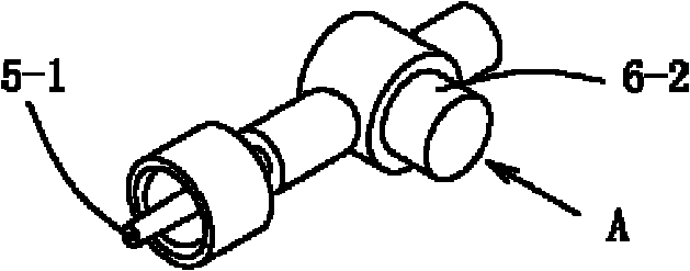
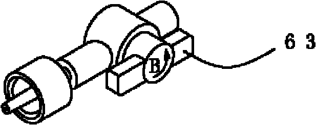
[0039] Disposable continuous negative pressure puncture device preferred embodiment, see figure 2 As in Example 1, the control hole can pass through the connecting pipe or not. The control hole in this embodiment is perpendicular to the through hole and runs through the connecting pipe. Cylinders connecting the side walls of pipes, such as figure 2 As shown in middle A, the cylinder moving laterally controls the connection and closure of the puncture needle and the needle tube through the connecting hole, and the shape of the cylinder matches the shape of the control hole, which is not limited to a cylinder, and can be rectangular or elliptical.


PUM

PropertyMeasurementUnit
Thicknessaaaaaaaaaa

Abstract

The invention discloses a dispensable continuous negative-pressure puncture outfit, which comprises a needle tube and a puncture needle, wherein a pintle is arranged in the needle tube; a stopping device is arranged between the puncture needle and the needle tube; at least one chute is arranged on the pintle axially; chute lateral plates are arranged on two sides of the chute; at least the chute plate on one side is provided with a locking groove; a locking clip is arranged on the end, in which the pintle is inserted, of the needle tube and can move up and down in the chute; and when the pintle is rotated, the locking clip is clipped in the locking groove to clip the pintle to prevent the pintle from moving down. Compared with the prior art, the puncture outfit has the advantages that: the structure is simple, the operation is convenient and ample sample can be accurately positioned and acquired, so the accuracy of fine needle aspiration cytopathologic diagnosis is improved greatly; the puncture time is reduce, pains suffered by patients are reduced, and an operator can concentrate to ensure puncture accuracy; and the drawback that the negative pressure is maintained by the traction force of the hand of the operator of the traditional puncture outfit is radically overcome, the operation is more flexible and quicker than the traditional puncture method, and a good needle feel is offered.

Description


Claims


Application Information

Patent Timeline
Owner 余小蒙
Learn More