
Hydraulic buffer

A technology of hydraulic buffers and liquid chambers, applied in the field of hydraulic buffers, can solve problems such as obstructing circulation and affecting the telescopic action of a piston rod, and achieve the effect of preventing discomfort

Active Publication Date: 2012-03-21
HITACHI ASTEMO LTD
View PDF1 Cites 0 Cited by
  • Summary
  • Abstract
  • Description
  • Claims
  • Application Information

AI Technical Summary

Problems solved by technology

[0005] However, in the prior art, there is a concern that, for example, discomfort may occur during the sliding stroke of the piston. If the piston collides with the bottom of the cylinder and the communication path is blocked, the flow in the bottom liquid chamber and the rod side liquid chamber will be hindered, affecting the piston rod. stretching action

Method used


Image

  • Hydraulic buffer
  • Hydraulic buffer
  • Hydraulic buffer

Examples


Embodiment Construction

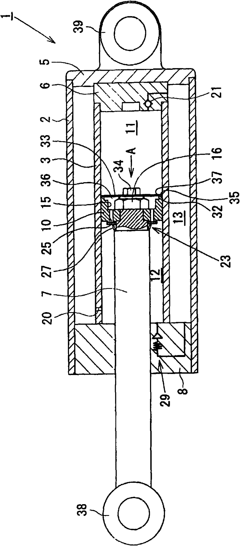
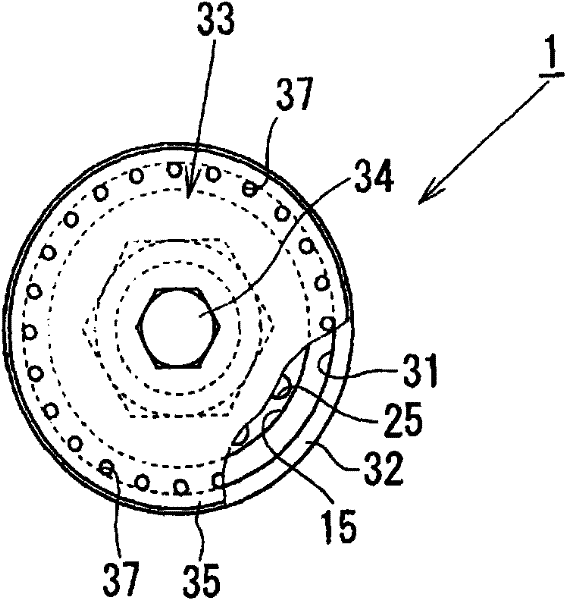
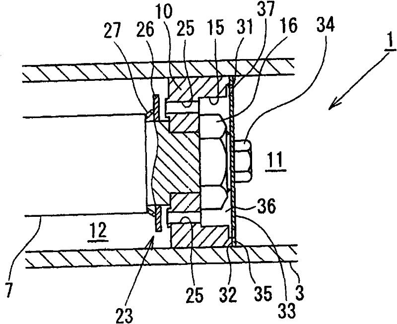
[0022] The following will be based on Figure 1-9 Preferred embodiments for implementing the present invention are described in detail. As an oil shock absorber using working oil as a working fluid, there is provided a hydraulic shock absorber according to an embodiment of the present invention. More specifically, the hydraulic damper according to the embodiment of the present invention can be used in a horizontal position, and is a so-called one-way flow type hydraulic damper in which hydraulic oil flows in only one direction. It can be used as a deflection shock absorber and left and right dynamic shock absorber for trolleys such as railway vehicles. Moreover, in the following introduction, for the convenience of introduction, the right side in the figure is taken as one end side, and the left side in the figure is taken as the other end side.

[0023] First, according to Figure 1~3 The oil shock absorber 1 of the first embodiment of the present invention will be describ...


PUM


Abstract

Provided is a hydraulic buffer, which can prevent unsmooth discharge of gas from a path, will not obstruct circulation inside a bottom side liquid chamber and a rod side liquid chamber even if the path is unsmooth, thereby the piston rod continues to telescope. An annular contact portion (32) projecting to the bottom side is formed on a side end portion of the bottom side liquid chamber (11) of apiston (10); a disc-shaped plate (33) is installed on the annular contact portion in an abut way; a plurality of interconnected pores (37) are formed at a position close to the annular contact portion on the plate (33); and the interconnected pores are opposite to a space (36) surrounded by the inner side of the annular contact portion (32) at the bottom side liquid chamber of the piston and the plate (33). Therefore, even though the piston impacts with the bottom (6), the piston rod (7) continues to telescope because the interconnected pores on the plate are not closed.

Description

technical field [0001] This invention relates to hydraulic shock absorbers used on railway vehicles and the like. Background technique [0002] Conventionally, in a hydraulic shock absorber, Patent Document 1 discloses a hydraulic shock absorber as a structure for discharging air in a cylinder, in which an annular plate is integrally provided on the end surface of a rod guide, and a gap is formed between the annular plate and the inner cylinder. A communication path is formed between them to communicate with the oil passage. When the piston rod expands and contracts, the gas mixed in the pressure oil in the rod side oil chamber is guided to the oil passage side through the communication path and discharged into the liquid storage chamber. [0003] Patent Document 1 Japanese Patent Application Laid-Open No. 11-13815 [0004] In addition, there is another method of arranging a disk-shaped plate on the piston, forming a concavo-convex portion on the plate to form a communicati...

Claims


Application Information

Patent Timeline
Patent Type & Authority Patents(China)
IPC IPC(8): F16F9/34
Inventor 柴原和晶
Owner HITACHI ASTEMO LTD
Learn More