
Sensor

A container and signal receiver technology, applied in instruments, measuring devices, measuring fluid pressure through electromagnetic components, etc., can solve problems such as diaphragm aging, achieve functional safety, improved life, and suitable applications.

Active Publication Date: 2013-07-17
MARQUARDT GMBH SCHLOSSTRASSE 16 7201 RIETHEIM-WEILHEIM 1 WEST GERMANY
View PDF0 Cites 0 Cited by
  • Summary
  • Abstract
  • Description
  • Claims
  • Application Information

AI Technical Summary

Problems solved by technology

In addition, the aging of the diaphragm is caused by the deposition of particles present in the fluid

Method used


Image

  • Sensor
  • Sensor
  • Sensor

Examples


Embodiment Construction

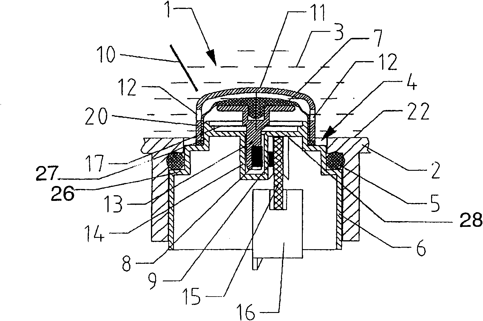
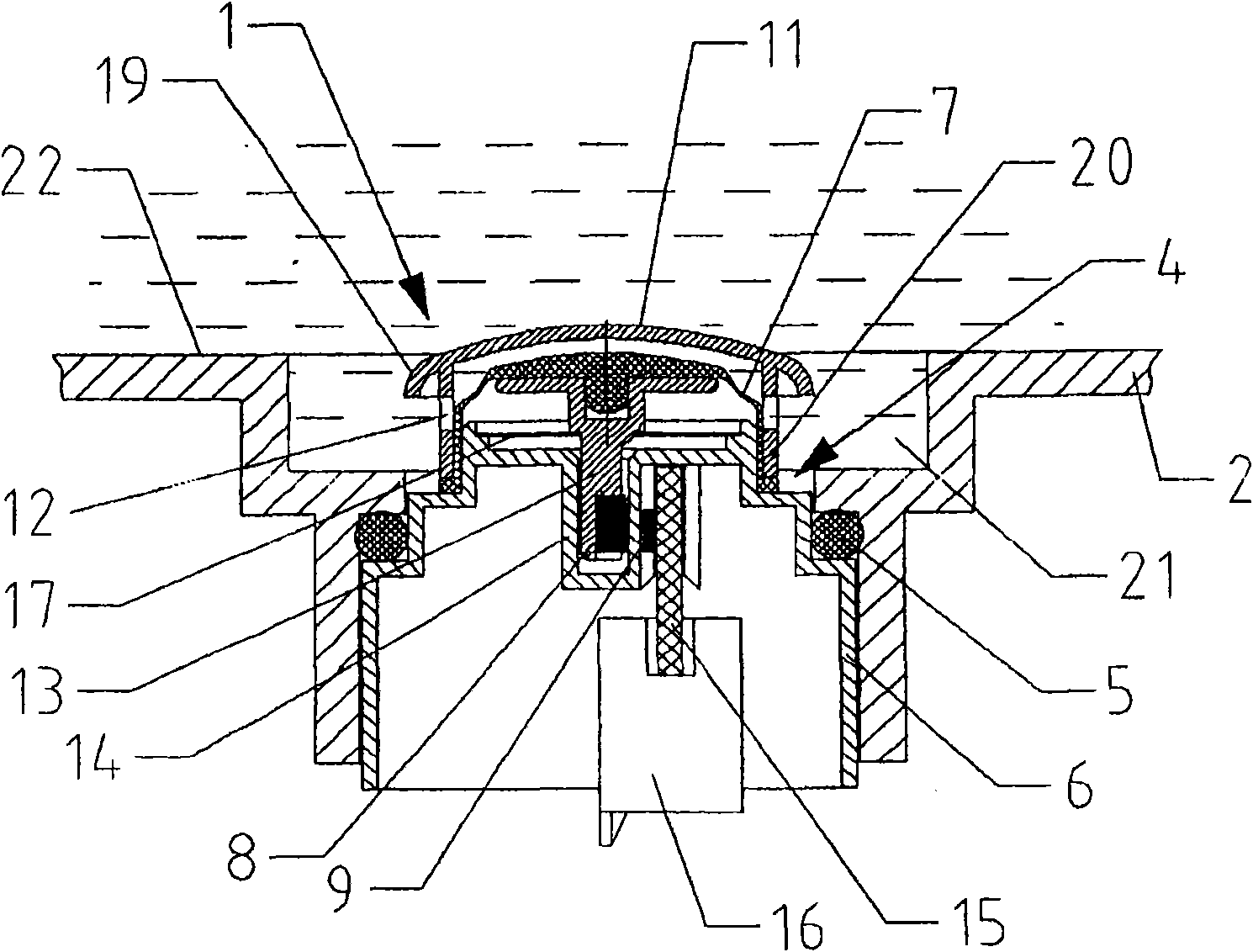
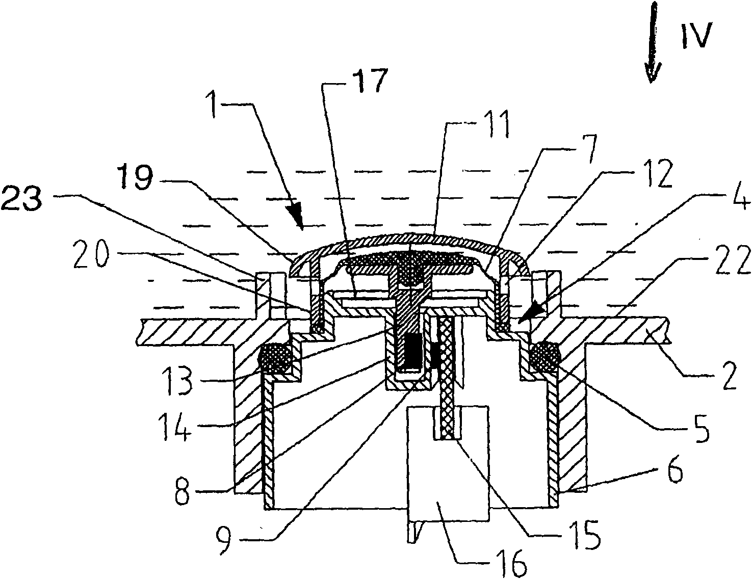
[0026] figure 1 A measuring device 1 for the medium to be measured can be seen in . Measuring device 1 is a pressure sensor for measuring washing liquid 3 , shown only schematically as a fluid, located in a washing tub of a washing machine designed as container 2 , wherein washing liquid 3 represents the medium to be measured. Measuring device 1 is inserted sealingly via seal 5 in drain pipe (Durchla β) 4 of washing tub 2 , so that measuring device 1 protrudes into washing liquid 3 located in washing tub 2 .

[0027] Measuring device 1 has a housing 6 , wherein a membrane 7 is arranged in and / or on housing 6 , which is in contact with washing liquid 3 . A signal generator 8, which may be a permanent magnet, is operatively connected to the diaphragm 7. Arranged in the housing 6 is a signal receiver 9 cooperating with a signal generator 8 which can be, for example, a Hall sensor. The signal receiver 9 generates a measurement signal corresponding to the position of the signal ...


PUM


Abstract

The invention relates to a measuring device (1), especially a sensor, such as a pressure sensor, a travel sensor or the like, comprising a housing (6) and a membrane (7) arranged in and / or on the housing (6). A signal transmitter (8) is actively connected to the membrane (7). A signal receiver (9) interacts with the signal transmitter (8). The membrane (7) is at least partially surrounded by a cover (11) especially a cap. The cover (11) has openings (12).

Description

technical field [0001] The invention relates to a measuring device for measuring a medium to be measured. Background technique [0002] The measuring device can be a sensor, such as a pressure sensor, a stroke sensor, or the like. Such measuring devices are mainly used for the direct measurement of operating parameters in fluids, for example in parts of domestic appliances where water is introduced. [0003] Measuring devices are known which have a housing and a membrane which is arranged in and / or on the housing and which is in contact with the medium. A signal generator is operatively connected to the membrane. A signal receiver cooperates with the signal generator to generate a measurement signal for the medium. It has been found that there is a risk of mechanical damage to the membrane by particles present in the fluid. The diaphragms of pressure sensors for measuring small pressures in dirty fluids are particularly sensitive. In addition, the membranes age due to t...

Claims


Application Information

Patent Timeline
IPC IPC(8): G01L19/06
CPCG01L19/0636G01L19/06G01L9/007
Inventor H·米勒F·坎普夫A·洛克海姆
Owner MARQUARDT GMBH SCHLOSSTRASSE 16 7201 RIETHEIM-WEILHEIM 1 WEST GERMANY
Learn More