Pressure reducing valve control

A pressure reducing valve and pilot valve technology, applied in the direction of fluid pressure control, auxiliary non-electric fluid pressure control, non-electric variable control, etc.

Inactive Publication Date: 2010-06-02
AQUAVENT UK
View PDF5 Cites 0 Cited by
  • Summary
  • Abstract
  • Description
  • Claims
  • Application Information

AI Technical Summary

Problems solved by technology

However, none of them actually solve the above problems and provide

Method used


Image

  • Pressure reducing valve control
  • Pressure reducing valve control
  • Pressure reducing valve control

Examples


Embodiment Construction

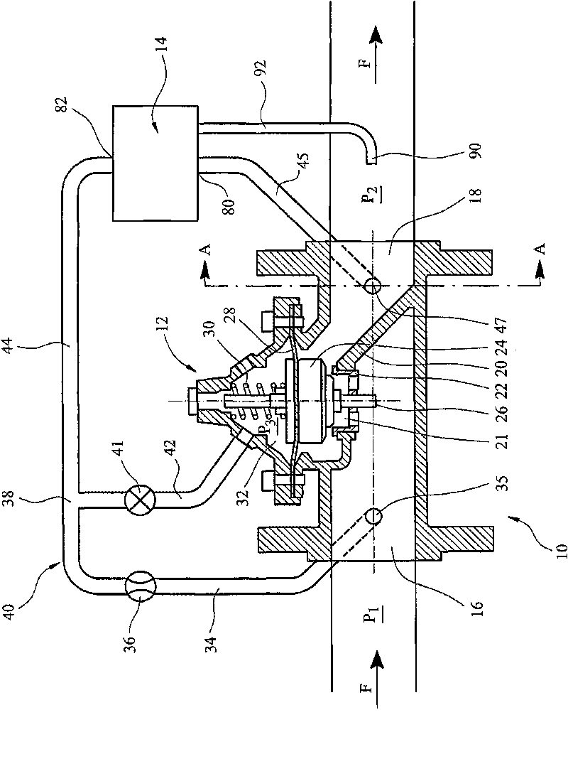
[0037] refer to figure 1 , the pressure reducing system 10 for water supply includes a primary pressure reducing valve (PRV) 12 and a pilot control valve 14 . The main PRV 12 is conventional and includes an inlet 16 and an outlet 18 connected to the water supply to carry water through the main valve 12 in the direction indicated by arrow F and to forwarded to consumers. Said inlet 16 and outlet 18 are interconnected by a valve seat 22 defining a bore 21 through a partition wall 20 of valve 12 . The valve body 24 is mounted on a valve stem 26 for movement toward and away from the valve seat 22 . The valve body 24 is mounted on a flexible diaphragm 28 above which is located a main valve bias spring 30 and a chamber referred to as a control volume 32 . The position of valve body 24 relative to valve seat 22 opens or closes valve 12 , thereby determining the pressure drop across valve 12 and between inlet 16 and outlet 18 . When the valve body 24 is close to the valve seat 22,...


PUM


Abstract

An improved pilot valve assembly (14) for hydraulically controlling a pressure reducing valve (12) to maintain and further vary the outlet pressure (P2) of the pressure reducing valve (12) in response to increased flow (f) through the valve (12). The pilot valve assembly (14) comprises first and second movable valve members (100, 102). The first and second moveable members (100,102) being acted on by a velocity head pressure sensed by a downstream Pitot tube (90) and a downstream outlet pressure (P2) in a balanced arrangement such that they move in response to both the velocity head and downstream pressure (P2) to open and close the pilot valve (14) and so main valve (12) to both maintain and vary the outlet pressure (P2).

Description

technical field [0001] The present invention relates to a pressure reducing valve (PRV), in particular to a pressure reducing valve for a water supply system. More particularly, the present invention relates to a method of controlling such valves through the use of a pilot valve arrangement, and in particular to a pilot valve arrangement that uses hydraulic methods to automatically sense Changes in flow, especially flow rates, and changes in valve settings. Background technique [0002] In supplying water from a source, the mains, to multiple end users, it is traditional practice to deliver the supply through PRVs which, for example, can reduce mains pressure from about 70 meters to about 15-20 meters. This is well worth it because the lower operating pressure reduces the leak rate, extends the life of the system, reduces the labor expenditure in repairing and maintaining the system, and reduces the frequency of mains bursts. [0003] Traditional PRV systems consist of a m...

Claims


Application Information

Patent Timeline
IPC IPC(8): G05D16/16
CPCG05D16/163Y10T137/7762
Inventor 理查德·詹姆士·赫尔利马克·尼古拉斯·洛克约翰·亨利·梅
Owner AQUAVENT UK
Why Eureka
Try Eureka