Diaphragm-type pressure reducing valve with high-pressure entering and low-pressure discharging

A pressure reducing valve, diaphragm type technology, applied in the direction of lift valve, valve details, safety valve, etc., can solve the problems of easy deformation of the valve seat, weak pressure bearing capacity, and reduced accuracy of the pressure reducing valve, so as to improve the overall strength, The effect of increasing the bearing pressure and increasing the bearing pressure

Pending Publication Date: 2020-02-28
昆山莱恒洁净材料有限公司
View PDF0 Cites 1 Cited by
  • Summary
  • Abstract
  • Description
  • Claims
  • Application Information

AI Technical Summary

Problems solved by technology

[0003] However, the ordinary diaphragm pressure reducing valve can only reach 3500 psig inflow and 500 psig in the outlet. There is only a single diaphragm in the ordinary diaphragm pressure reducing valve, and the single diaphragm is easy to deform and rupture when the pressure is too high, resulting in bearing failure. The pressure capacity is weak. The combination of a single compression nut and a valve seat in the valve will cause the valve seat to be easily deformed after the intake pressure increases, which will reduce the precision of the pressure reducing valve and also lead to the weak pressure bearing capacity of the pressure reducing valve.

Method used


Image

  • Diaphragm-type pressure reducing valve with high-pressure entering and low-pressure discharging
  • Diaphragm-type pressure reducing valve with high-pressure entering and low-pressure discharging
  • Diaphragm-type pressure reducing valve with high-pressure entering and low-pressure discharging

Examples


Embodiment

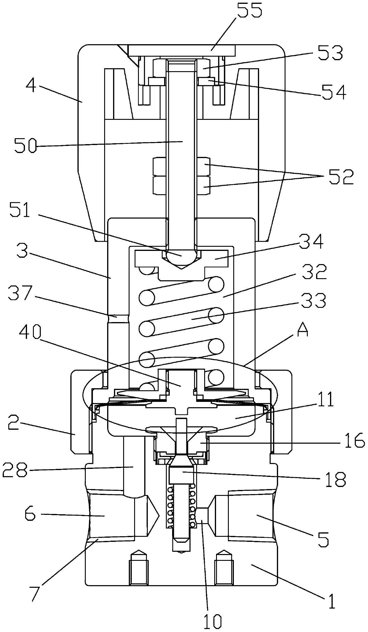
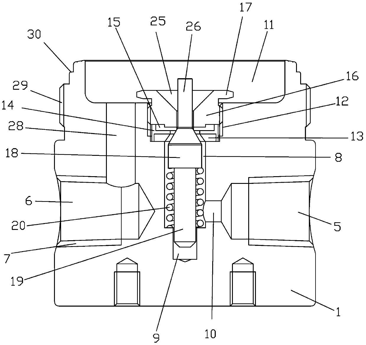
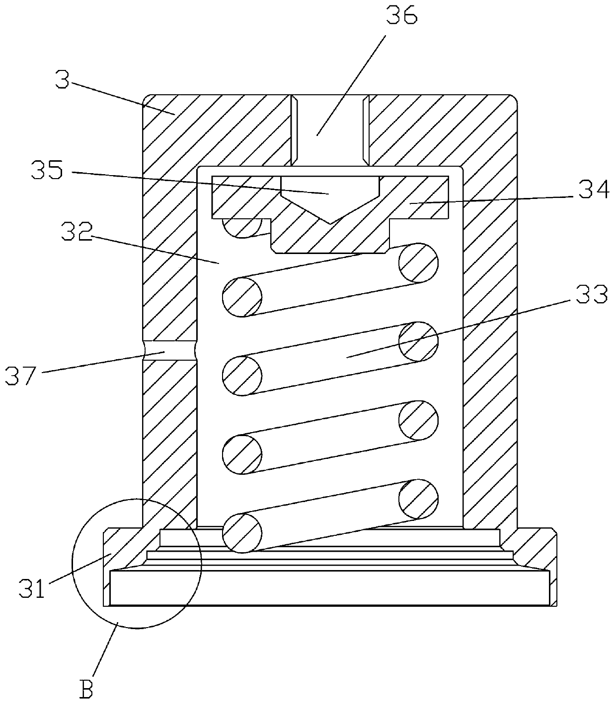
[0025] Embodiment: a kind of diaphragm pressure reducing valve that enters high pressure and exits low pressure, such as Figure 1-Figure 10 As shown, it includes a pressure reducing valve body, a bonnet nut, a bonnet and a handle, and is characterized in that the lower right side of the pressure reducing valve body is provided with an air inlet hole, and the lower left side of the pressure reducing valve body is provided with an air outlet hole , the inner rings of the air inlet hole and the air outlet hole are provided with internal threads, the middle part of the pressure reducing valve body is vertically provided with a valve stem cavity, and the center of the bottom of the valve stem cavity is provided with a valve stem pin positioning hole, The outer diameter of the valve stem pin positioning hole is smaller than the inner diameter of the valve stem cavity, and a first vent hole is provided between the lower right side of the valve stem cavity and the air intake hole, and...


PUM


Abstract

The utility model relates to a diaphragm-type pressure reducing valve with high-pressure entering and low-pressure discharging, and belongs to the technical field of diaphragm-type pressure reducing valves. A compression nut sealing element, a valve seat bearing seat and a valve seat are fixed in a compression nut fixing hole by a compression nut. When the valve seat bearing seat is pressed by thecompression nut, the upper end surface of the valve seat bearing seat abuts against the lower end surface of the compression nut, and the lower end surface of the valve seat bearing seat abuts against on the bottom end surface of the compression nut fixing hole. When the valve seat bearing seat is fixed, the valve seat and the compression nut seal are supported at the same time, so that the valveseat bearing seat greatly increases the pressure-bearing force of the valve seat, and it is guaranteed that the valve seat can bear he high-pressure impact of air inlet 6,000 psig for log time; a diaphragm sleeve is arranged, the overall strength of a diaphragm is improved, and the pressure bearing is improved; and the diaphragm and the diaphragm sleeve are tightly pressed on a lower seat of thediaphragm by an upper seat of the diaphragm, and the outer periphery edges of the diaphragm and the diaphragm sleeve are locked and fixed by a diaphragm compression steps and outer periphery surface of the upper end of a pressure reducing valve body. The diaphragm-type pressure reducing valve with high-pressure entering and low-pressure discharging can achieve the effects that the air inlet can reach 6,000 psig and the air output can reach 750 psig.

Description

technical field [0001] The invention belongs to the technical field of diaphragm pressure reducing valves, and in particular relates to a diaphragm type pressure reducing valve that enters high pressure and outputs low pressure. Background technique [0002] The pressure reducing valve is a valve that reduces the inlet pressure to a certain outlet pressure by adjusting, and relies on the energy of the medium itself to automatically maintain the outlet pressure. From the point of view of fluid mechanics, the pressure reducing valve is a throttling element whose local resistance can be changed, that is, by changing the throttling area, the flow velocity and the kinetic energy of the fluid are changed, resulting in different pressure losses, so as to achieve the purpose of decompression. The pressure reducing valve relies on the adjustment of the control and regulation system to balance the fluctuation of the pressure behind the valve with the spring force, so that the pressure...

Claims


Application Information

Patent Timeline
IPC IPC(8): F16K17/30F16K31/60F16K27/02F16K1/42F16K1/32
CPCF16K1/32F16K1/42F16K17/30F16K27/02F16K31/60
Inventor 谢建锋陈建安颜奇荣
Owner 昆山莱恒洁净材料有限公司
Why Eureka
Try Eureka