
Machining device for high-precision servo motor brake disc

A processing device and servo motor technology, applied in metal processing equipment, metal processing machinery parts, manufacturing tools, etc., can solve problems such as damage and low processing efficiency, and achieve the goal of increasing bearing pressure, improving processing efficiency, and improving drilling efficiency Effect

Pending Publication Date: 2021-11-09
QINGDAO FENGGUANG PRECISION MACHINERY
View PDF0 Cites 4 Cited by
  • Summary
  • Abstract
  • Description
  • Claims
  • Application Information

AI Technical Summary

Problems solved by technology

[0002] An existing device for processing brake discs of high-precision servo motors needs to drill holes in the brake discs when processing the brake discs, and the temperature in a certain range around the drilling holes is relatively high. Drilling the disc will cause some damage to it. At the same time, whether it is neatly or randomly drilling the brake disc, it is difficult to avoid drilling the brake disc multiple times in a local area. When a single drilling produces The higher the temperature, the larger the area around the drilled hole that cannot be drilled next time, and the larger the vibration frequency and the corresponding drilled hole diameter of the brake disc during the drilling process, the corresponding The range that needs to be avoided is also larger. At the same time, when the existing processing device for high-precision servo motor brake discs processes the brake disc, if it waits for the cooling around the drilling hole before processing, the processing efficiency is low. Therefore, , it is necessary to design a high-precision servo motor brake disc processing device to protect the brake disc and improve the processing efficiency

Method used


Image

  • Machining device for high-precision servo motor brake disc
  • Machining device for high-precision servo motor brake disc
  • Machining device for high-precision servo motor brake disc

Examples


Embodiment Construction

[0039] The following will clearly and completely describe the technical solutions in the embodiments of the present invention with reference to the accompanying drawings in the embodiments of the present invention. Obviously, the described embodiments are only some, not all, embodiments of the present invention. Based on the embodiments of the present invention, all other embodiments obtained by persons of ordinary skill in the art without making creative efforts belong to the protection scope of the present invention.

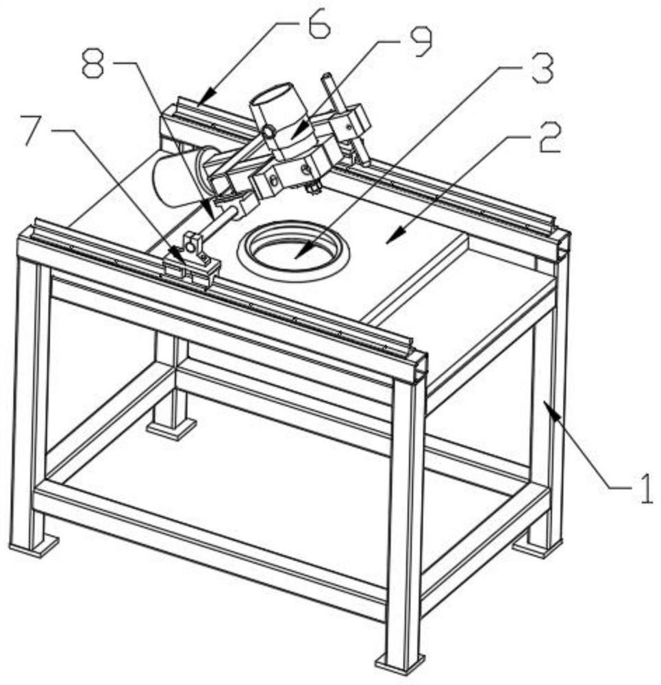
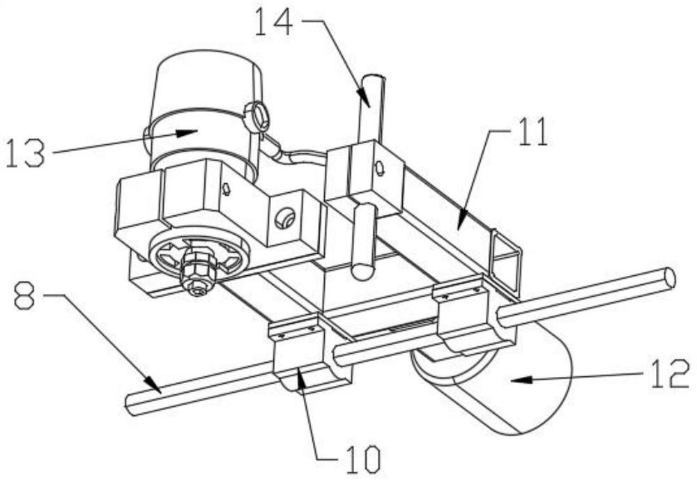
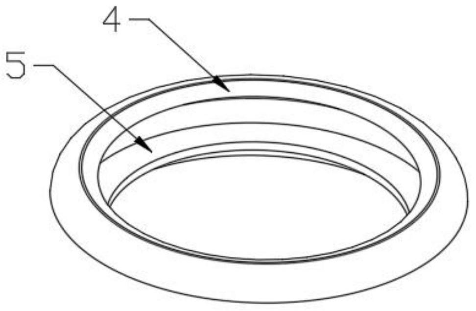
[0040] see Figure 1-4 , the present invention provides a technical solution: a high-precision servo motor brake disc processing device, including a support frame 1 and a data management module, characterized in that: the data management module includes a data detection module and a data processing module, and the data detection module is used To detect the real-time status of the device during operation, and transmit the data information to the data processin...


PUM


Abstract

The invention discloses a machining device for a high-precision servo motor brake disc. The device comprises a support frame and a data management module, wherein the data management module comprises a data detection module and a data processing module; the data detection module is used for detecting the real-time state of the device during operation, and transmitting data information to the data processing module; the data processing module is used for processing the received data information and controlling the device according to the processing result; a fixing plate is fixedly installed on the support frame; a limiting groove is formed in the center of the fixing plate, an elastic limiting piece is fixedly installed at the top of the limiting groove, and a fixed baffle is arranged at the bottom of the limiting groove; sliding rails are arranged at the two sides of the support frame; sliding blocks are connected to the tops of the sliding rails in a sliding manner; and rotary connecting rods are connected to the tops of the sliding blocks through bearings. The machining device has the characteristics that the brake disc is protected and the machining efficiency is improved.

Description

technical field [0001] The invention relates to the technical field of brake disc processing, in particular to a brake disc processing device for high-precision servo motors. Background technique [0002] An existing device for processing brake discs of high-precision servo motors needs to drill holes in the brake discs when processing the brake discs, and the temperature in a certain range around the drilling holes is relatively high. Drilling the disc will cause some damage to it. At the same time, whether it is neatly or randomly drilling the brake disc, it is difficult to avoid drilling the brake disc multiple times in a local area. When a single drilling produces The higher the temperature, the larger the area around the drilled hole that cannot be drilled next time, and the larger the vibration frequency and the corresponding drilled hole diameter of the brake disc during the drilling process, the corresponding The range that needs to be avoided is also larger. At the...

Claims


Application Information

Patent Timeline
Patent Type & Authority Applications(China)
IPC IPC(8): B23B41/00B23Q17/09G05B19/4065
CPCB23B41/00B23Q17/09B23Q17/0952B23Q17/0985B23Q17/0971B23Q17/099G05B19/4065
Inventor 李伟
Owner QINGDAO FENGGUANG PRECISION MACHINERY
Learn More