Phase diversity wave front measurement imaging device based on difference optics

A technology of phase difference method and imaging device, which is applied in the direction of measuring device, optical radiation measurement, phase influence characteristic measurement, etc., which can solve problems such as difficulty in ensuring true and accurate measurement and restoration results, difficulty in achieving complete synchronization, loss of light energy, etc. Achieve reliable data acquisition method, solve the effect of low signal-to-noise ratio, simple and stable structure

Active Publication Date: 2012-08-15
INST OF OPTICS & ELECTRONICS - CHINESE ACAD OF SCI
View PDF2 Cites 16 Cited by
  • Summary
  • Abstract
  • Description
  • Claims
  • Application Information

AI Technical Summary

Problems solved by technology

[0004] However, according to the principle of the PD algorithm, at least two images of the focal plane and the defocus plane of the same target are required to be collected at the same time, which makes the currently used PD optical imaging system have many limitations.
For example (1) an imaging system that utilizes two photodetector CCDs to collect images of the focal plane and the defocused plane respectively (Chinese patent, a human eye phase difference measurement system based on phase difference, Xuan Li, Li Dayu, Kong Ningning, etc., publication number: CN20205027561U, 2011.11), it is necessary to simultaneously image the same target by means of external triggering, so on the one hand, higher requirements are put forward on the external triggering circuit, and it is difficult to achieve complete synchronization; on the other hand, it is impossible to guarantee the exposure gain, quantum The efficiency and noise level are close to the same, which makes it difficult for the collected data to reflect the real focus plane and defocus plane images, which seriously affects the measurement accuracy and restoration results of PD in practical applications; (2) using traditional spectroscopic technology to pass a photoelectric detection An imaging system that collects images of the focal plane and the defocused plane at the same time with CCD (Yu Xuegang, design of phase difference wavefront detector [M]. Master's Degree Thesis of Graduate School of Chinese Academy of Sciences. 2008; Chinese patent, a phase difference based on combined prism Differential wavefront sensor, Luo Qun, Rao Changhui, Wang Xiaohua, etc., application number: 201210027766.X, 2012.02), this type of method usually uses a beam splitter or a combination of a beam splitter prism and a reflective prism to control the focal plane and the out-of-focus plane beam projected to a Photodetector CCD target surface, but there are the following disadvantages: there is light energy loss when the beam passes through the beam splitter, which greatly restricts the use of PD in low light conditions; it cannot provide a gradually adjustable defocus from zero , in actual application, it is impossible to provide a suitable defocused surface image for PD, and it is difficult to ensure the true and accurate measurement and restoration results; there are multiple reflective surfaces in the combination of beam splitting prisms, which puts high requirements on the processing of micro-optical components, otherwise every Each surface will introduce additional unknown phase difference to the imaging system, which will seriously affect the algorithm results

Method used


Image

  • Phase diversity wave front measurement imaging device based on difference optics
  • Phase diversity wave front measurement imaging device based on difference optics
  • Phase diversity wave front measurement imaging device based on difference optics

Examples


Embodiment Construction

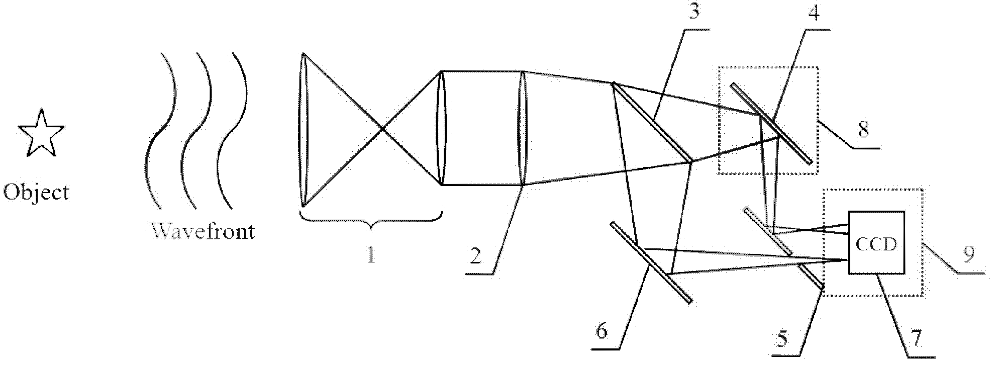
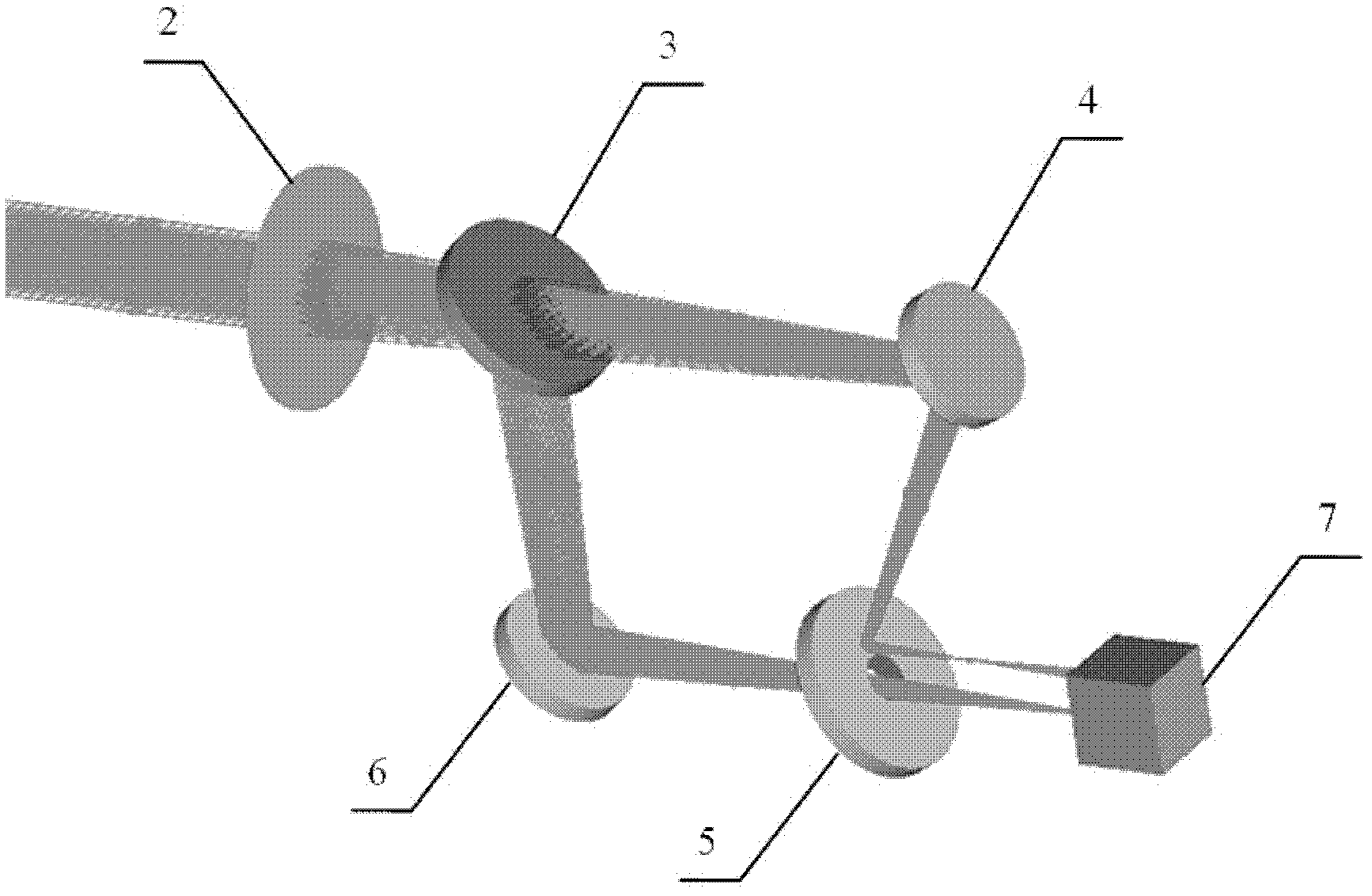
[0024] Such as figure 1 As shown, the present invention consists of a beam matching system 1, an imaging lens 2, a beam splitter 3, a first reflector 4, a reflector 5 with a small hole, a second reflector 6, a photodetector CCD 7, and a first translation mechanism 8. The second translation mechanism 9 is formed. The light wave emitted by the target to be imaged passes through the beam matching system 1 and the imaging lens 2 to the beam splitter 3, and the beam splitter 3 divides the light wave into two beams (the light intensity ratio of the two beams can be adjusted by replacing the beam splitter 3 with a different beam splitting ratio) , wherein a beam of light (as the focal plane beam) is reflected by the second reflector 6, and passes through the aperture in the reflector 5 with the aperture to reach the photodetector CCD7; another beam of light (as the out-of-focus beam) ) are respectively reflected to the photodetector CCD7 by the first reflector 4 and the reflector 5 ...


PUM


Abstract

The invention discloses a phase diversity wave front measurement imaging device based on difference optics, which comprises a light beam matching system, an imaging lens, a spectroscope, a reflecting mirror, a reflecting mirror with small holes, a translation mechanism and a photoelectric detector CCD (charge-coupled device). The phase diversity wave front imaging device is characterized that a difference optics system can simultaneously obtain a focal plane image and an out-of focal plane image of the same target by a photoelectric detector; the light intensity energy of a target to be imaged can not be lost; an out-of focal plane can obtain continuous adjustable out-of focusing amount which increases from zero gradually; and the positions of the focal plane image and the out-of focal plane image in a target surface of the photoelectric detector CCD can be adjusted randomly. Compared with the various imaging technologies used in phase diversity, the phase diversity wave front measurement imaging device is simple and stable in structure, can simultaneously obtain the focal plane image and the out-of focal plane image by the photoelectric detector, can flexibly adjust various parameters used for the phase diversity, can realize maximum light energy utilization, and establish a foundation for a phase diversity wave front measurement technology in actual engineering, particularly an application of the phase diversity wave front measurement technology under a weak light condition.

Description

technical field [0001] The invention relates to a wavefront measurement and imaging device, in particular to a wavefront measurement and imaging device based on differential optics phase difference method. Background technique [0002] The wave front aberration will distort the wave front of the incident light beam, thereby greatly reducing the resolution and imaging quality of the optical imaging system. Since the 1950s, people have proposed adaptive optics technology (Adaptive Optics, AO), which has effectively improved the imaging quality of optical imaging systems, especially ground-based telescopes. However, limited by the detection accuracy of the wavefront sensor, the limited correction capability of the deformable mirror and the limited bandwidth of the control loop, the correction of the wavefront distortion by the AO system is partial, and the corrected result is still affected by the residual phase difference, serving the AO The post-processing method of system i...

Claims


Application Information

Patent Timeline
Patent Type & Authority Applications(China)
IPC IPC(8): G01J9/00G01N21/41
Inventor 鲍华饶长辉李梅
Owner INST OF OPTICS & ELECTRONICS - CHINESE ACAD OF SCI
Why Eureka
Try Eureka