
Ceramic electric kettle

A technology for electric kettles and ceramics, which is applied to water-boiling utensils, cooking utensils, household appliances, etc. It can solve the problems of affecting the appearance, uncontrollable dimensional accuracy, and lower product grades, so as to reduce the difficulty and cost of the manufacturing process and have a beautiful appearance. Generosity, the effect of improving product quality

Inactive Publication Date: 2010-06-09
丁国盛
View PDF0 Cites 8 Cited by
  • Summary
  • Abstract
  • Description
  • Claims
  • Application Information

AI Technical Summary

Problems solved by technology

[0004] 1. Opening a through hole directly on the body of the ceramic pot will affect the overall appearance of the pot and reduce the grade of the product;
[0005] 2. Due to the use of ceramic materials, the through holes on the side wall of the pot body cannot be integrally formed when making the pot body, but need to be manually pierced separately, which is not only difficult to process, but also easily causes ceramic waste products, and due to the low precision of manual processing, The appearance of the processed through holes is not neat enough, which affects the overall appearance of the pot body
[0006] 3. In addition, because the dimensional accuracy of ceramic products cannot be controlled very accurately during the manufacture, the matching accuracy between the bottom of the pot body and the bottom of the pot is low. There is often a certain deviation at the junction of the two, forming a gap, which affects Appearance or cause unstable combination

Method used


Image

  • Ceramic electric kettle
  • Ceramic electric kettle
  • Ceramic electric kettle

Examples


Embodiment Construction

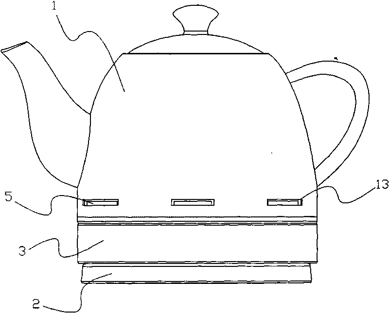
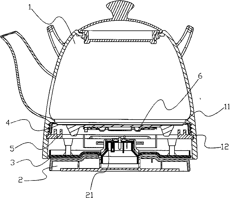
[0018] refer to figure 2 , the ceramic electric kettle provided by the present invention comprises a kettle body 1 and a power base 2, a kettle bottom 3 is provided at the bottom of the kettle body 1, a heating plate 4, a fixing snap ring 5 and a heating plate 4 are arranged between the kettle bottom 3 and the kettle body 1 The thermostat 6 and the heating plate 4 are structures used for electric heating, and its structure is the same as that of common electric kettles. For example, in order to obtain a better sealing effect, sealing silica gel and the inside of the kettle body 1 can be arranged on the outer periphery of the heating plate 4 Contact, after the heating disc 4 is installed in the kettle body 1, it is clamped in the kettle body 1 by the fixing snap ring 5.

[0019] Wherein, the annular slot 12 is arranged on the inner wall of the pot body 1 at 360 degrees, which makes the process simple and ensures a good installation effect at the same time.

[0020] Such as ...


PUM


Abstract

The invention relates to a ceramic electric kettle which comprises a kettle body and a power supply base, wherein the bottom of the kettle body is provided with a kettle bottom; a heating disk and a fixed clamping ring are arranged between the kettle bottom and the kettle body; a connector for connecting the kettle bottom is arranged on the power supply base; a convex clamping step is arranged on the inner wall of the lower part of the kettle body; an annular clamping groove is arranged on the inner wall of the kettle body which is positioned under the clamping step; the fixed clamping ring is clamped on the annular clamping groove; the heating disk is clamped between the clamping step and the fixed clamping ring; the fixed clamping ring is fixedly connected with the kettle bottom under the fixed clamping ring; and the kettle bottom is arranged in the side wall of the bottom of the kettle body. Compared with a through hole type bayonet structure of the original product, the outer wall of the kettle body can not be provided with holes; accordingly, the appearance of the kettle body is more neat and beautiful, a manufacturer can set the appearance and a decorative pattern of the ceramic kettle body easily, and the appearance diversity of the ceramic electric kettle is improved; the annular clamping groove does not need manual processing, the manufacture process difficulty and cost of the product are reduced, the waste probability is reduced, and the product is more beautiful.

Description

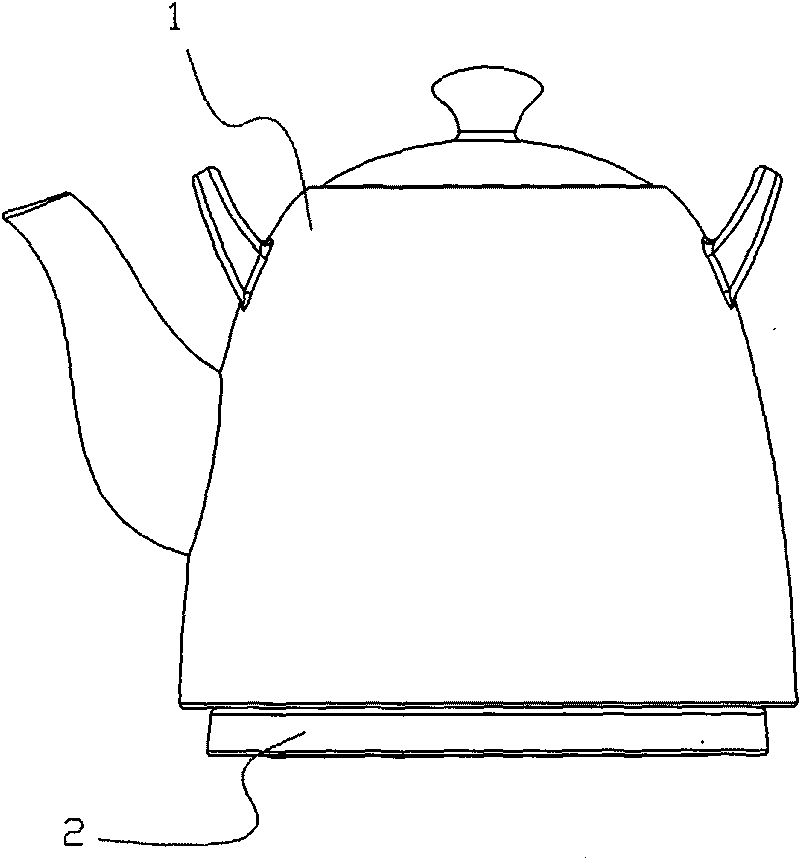
technical field [0001] The invention relates to an electric kettle, in particular to a ceramic electric kettle. Background technique [0002] At present, there is a type of ceramic electric heating kettle on the market. The body of the kettle is made of ceramic materials. This type of kettle is environmentally friendly, durable, non-corrosive, non-absorbent, and beautiful in appearance. It is a water heating appliance with good market response; such as figure 1 As shown, the existing ceramic electric kettle is mainly composed of a pot body 1 made of ceramics, a pot bottom 3, a heating plate for heating, and a power base 2. The power base 2 is provided with a connector for connecting with the bottom of the pot. 3 connection, the bottom of the pot body 1 is provided with a thermostat to control the heating plate, and is encapsulated in the pot body 1 by the pot bottom 3. When the pot bottom 3 is installed on the power base through the connector 21, the thermostat is connected ...

Claims


Application Information

Patent Timeline
Patent Type & Authority Applications(China)
IPC IPC(8): A47J27/21A47J36/00
Inventor 丁国盛
Owner 丁国盛
Learn More