Movable power supply device of light source and method thereof

A power supply device and movable technology, applied in the direction of electric light sources, lighting devices, circuit layout, etc., can solve the problems of general products and methods without suitable structures and methods, not easy to reuse, limited power lines and configurations, etc. Achieving simplified assembly and reuse, and a wide range of applications

Inactive Publication Date: 2012-01-18
FRONTEND ANALOG & DIGITAL TECH CORP
View PDF0 Cites 0 Cited by
  • Summary
  • Abstract
  • Description
  • Claims
  • Application Information

AI Technical Summary

Problems solved by technology

[0006] Although the above-mentioned external design suitable for disassembly has its effect, it also has an unavoidable problem, that is, its power line and configuration are still limited. No matter how the modules are combined, the power line still needs to be planned and designed in advance, otherwise it will also be The problem of planning errors; on the other hand, the above-mentioned power lines and configurations will be made into special sizes and collocations, which are also not easy to reuse
[0007] It can be seen that the above-mentioned existing light source power supply device and method thereof obviously still have inconvenience and defects in product structure, method and use, and need to be further improved urgently.
In order to solve the above-mentioned problems, the relevant manufacturers have tried their best to find a solution, but no suitable design has been developed for a long time, and there is no suitable structure and method for general products and methods to solve the above-mentioned problems. This is obviously a problem that relevant industry players are eager to solve

Method used


Image

  • Movable power supply device of light source and method thereof
  • Movable power supply device of light source and method thereof
  • Movable power supply device of light source and method thereof

Examples


Embodiment Construction

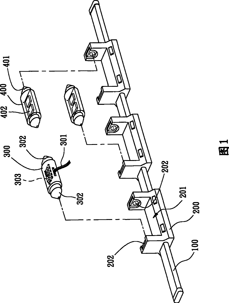
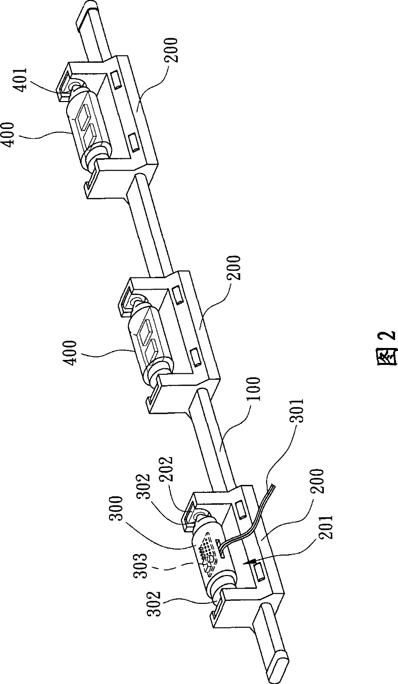
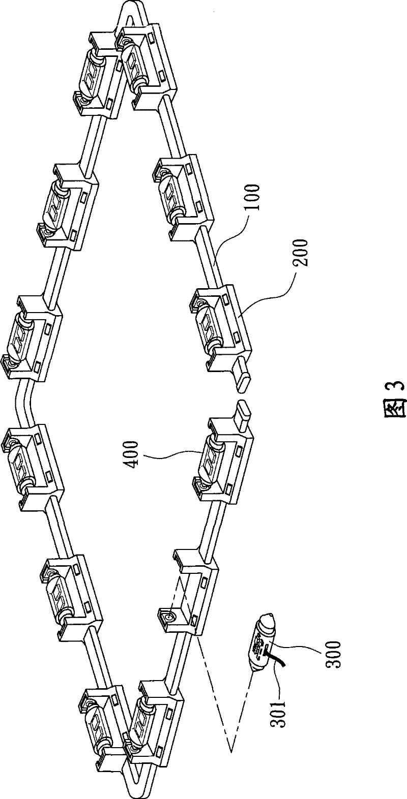
[0068] In order to further explain the technical means and effects of the present invention to achieve the intended purpose of the invention, the specific implementation and structure of the active power supply device and method for the light source proposed according to the present invention will be described below in conjunction with the accompanying drawings and preferred embodiments. , method, step, feature and effect thereof, detailed description is as follows.

[0069] The aforementioned and other technical contents, features and effects of the present invention will be clearly presented in the following detailed description of preferred embodiments with reference to the drawings. Through the description of the specific implementation mode, a more in-depth and specific understanding of the technical means and effects adopted by the present invention to achieve the intended purpose can be obtained. However, the accompanying drawings are only for reference and description, ...


PUM


Abstract

The invention relates to a movable power supply device of a light source and a method thereof. The movable power supply method of the light source comprises the steps of connecting a plurality of connecting seats by at least one independent bearing circuit having no power, wherein the connecting seats are used for mounting and dismounting the light source or power supply connectors correspondingly; and maintaining any one connecting seat for mounting the power supply connector on the bearing circuit so as to realize the light source power circulation of the connecting seats on the bearing circuit. The movable power supply device of the light source comprises the bearing circuit, a plurality of the connecting seats, at least one power supply connector and at least one light source, or comprises a plurality of the bearing circuits, a plurality of connecting seats, at least one power supply connector and at least one extension line, thereby replacing power supply connection and configuration modes at any time by the application of the method and the device. The invention goes beyond the technical set pattern of previously wiring and can simply reuse the devices.

Description

technical field [0001] The invention relates to a design of a power supply device for a light source, in particular to a movable power supply device for a light source and a method thereof that can simplify the conventional pre-wiring technology and allow all equipment to be easily reused. Background technique [0002] Currently, the design of power supply units for commercially available light sources can be roughly divided into two types: the first type is to fix the light source and power supply during the indoor and outdoor decoration or product manufacturing process, and the second type is an external design suitable for disassembly. [0003] Among them, the type of fixing the light source and power supply during the interior and exterior decoration or product manufacturing process is the most common type. The design must properly arrange the light source configuration, power circuit connection and wiring before decoration or product production, and after decoration, pro...

Claims


Application Information

Patent Timeline
Patent Type & Authority Patents(China)
IPC IPC(8): F21S4/00F21V23/06
Inventor 叶长青
Owner FRONTEND ANALOG & DIGITAL TECH CORP
Why Eureka
Try Eureka