Debugging remote controller

A technology for remote control and remote control reception, applied in the field of remote control, can solve the problems of low efficiency and cumbersome TV work.

Inactive Publication Date: 2010-06-09
SHENZHEN SKYWORTH RGB ELECTRONICS CO LTD
View PDF0 Cites 5 Cited by
  • Summary
  • Abstract
  • Description
  • Claims
  • Application Information

AI Technical Summary

Problems solved by technology

[0003] The purpose of the present invention is to provide a remote control for debugging, aiming at solving the problems of cumbersome work and low efficiency when debugging TV sets

Method used


Image

  • Debugging remote controller
  • Debugging remote controller
  • Debugging remote controller

Examples


Embodiment Construction

[0024] In order to make the object, technical solution and advantages of the present invention clearer, the present invention will be further described in detail below in conjunction with the accompanying drawings and embodiments. It should be understood that the specific embodiments described here are only used to explain the present invention, not to limit the present invention.

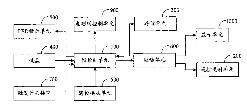
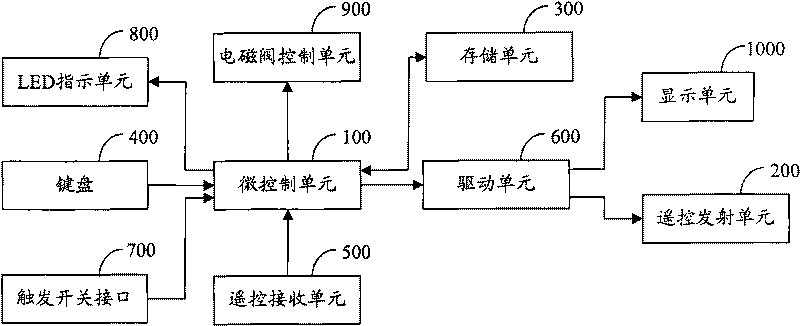
[0025] figure 1 The structure of the debugging remote controller provided by the embodiment of the present invention is shown.

[0026] The remote controller for debugging includes a micro-control unit 100, a remote-control transmitter unit 200 for transmitting control codes, and a storage unit 300 for storing control codes. and trigger switch interface 700.

[0027] The user sends the mode control signal to the micro control unit 100 through the keyboard 400, and the micro control unit 100 controls and debugs the remote controller to be in the learning mode or the remote control mode according t...


PUM


Abstract

The invention is applied to the technical field of remote controllers, and provides a debugging remote controller. The debugging remote controller comprises a micro control unit, a remote control sending unit, a storage unit, a keyboard, a remote control receiving unit, a trigger switch interface and a driving unit. Once the debugging remote controller receives a trigger signal, a control code which is stored in the storage unit in advance is sent to a television and then the television is debugged. Due to the automatic debugging way, the debugging work is simple and the working efficiency is promoted.

Description

technical field [0001] The invention belongs to the technical field of remote controllers, and in particular relates to a debugging remote controller. Background technique [0002] At present, in the mass production of TV sets, workers at different stations have different debugging items for TV sets. For example, this station debugs TVs in TV state, while the next station debugs TVs in AV state. for debugging. When the workers at each station debug the TV, they debug the TV by debugging the remote control. When the workers at a certain station need to debug multiple debugging items of the TV, The worker presses the remote control button several times to debug the TV, which is very cumbersome and inefficient. Contents of the invention [0003] The purpose of the present invention is to provide a remote controller for debugging, aiming at solving the problems of cumbersome work and low efficiency when debugging TV sets. [0004] The present invention is achieved in this w...

Claims


Application Information

Patent Timeline
Patent Type & Authority Applications(China)
IPC IPC(8): G08C23/04H04N17/04
Inventor 王勇卓成钰
Owner SHENZHEN SKYWORTH RGB ELECTRONICS CO LTD
Why Eureka
Try Eureka