
Electric connector and locking device thereof

An electrical connector and locking device technology, applied in the direction of connecting/disconnecting connecting parts, parts of connecting devices, connection, etc. The effect of reducing production control costs, simplifying the lock structure, and easy mold opening

Active Publication Date: 2010-06-09
东莞胡连电子科技有限公司 +1
View PDF2 Cites 3 Cited by
  • Summary
  • Abstract
  • Description
  • Claims
  • Application Information

AI Technical Summary

Problems solved by technology

However, the obvious deficiency of this solution is that the joystick of the cover is only connected to the side wall by a small rotation point, and is easy to break, so that after the joystick is separated from the cover, the locking effect is lost
Moreover, the locking mechanism between the cover and the side wall of the contact carrier module is too complicated, difficult to open the mold, and has high dimensional precision, which consumes too high production control costs, and needs to be improved urgently

Method used


Image

  • Electric connector and locking device thereof
  • Electric connector and locking device thereof
  • Electric connector and locking device thereof

Examples


Embodiment Construction

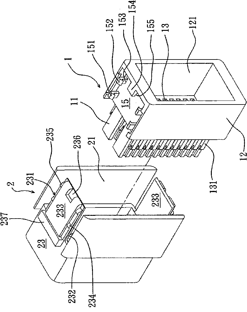
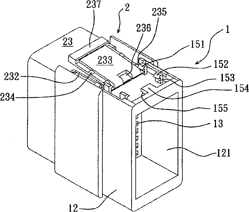
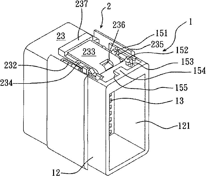
[0055] An electrical connector with a locking device is used as an example for illustration below, and the specific structure of the locking device can be obtained from this embodiment. Such as figure 1 and Figure 4 As shown, basically, the electrical connector of the present invention includes a body 1 and a positioning cover 2 . Wherein, the body 1 and the positioning cover constitute the locking device of the electrical connector of the present invention.

[0056] The body 1 is made of insulating material, such as plastic. A joint portion 11 protrudes from the rear of the main body 1, and the front of the joint portion 11 is integrally connected with a larger skirt portion 12, and an accommodating space 121 is provided inside the skirt portion 12 for the traditional sealing ring and grille. Accommodating and positioning, the sealing ring and the grille are traditional components, which will not be described in detail here. Wherein, the joint portion 11 is used for dock...


PUM


Abstract

The invention relates to an electric connector locking device which comprises a body and a positioning cover that are mutually sleeved, wherein a rail formed by at least one pair of guide hooks at a left side and a right side is arranged on the lateral wall of the body so as to be beneficial to the penetration of an insertion piece which extends from the front side of the lateral wall of the positioning cover; the insertion piece is a tongue piece which extends backwards and obliquely at the front end of a basal plate, an oblique included angle is arranged between the basal plate and the tongue piece so that a backstop edge at the rear end of the tongue piece is converted into a flat and straight state from a tilting state after at least one pair of blocking hooks at the left and right sides of the tongue piece are buckled and pressed by the guide hooks arranged oppositely so as to be beneficial to promoting a splicing piece inside the positioning cover to press a pressing piece of a terminal slot inside the body to deform, therefore, all contact terminals are positioned and locked in the terminal slot so as to be beneficial to promoting the combination between a complementary connector and the electric connector.

Description

technical field [0001] The invention relates to an electrical connector, in particular to an electrical connector with a locking device and the locking device. Background technique [0002] The use of electrical connectors in electrical products is very common, and its main purpose is to conduct power or signals. Therefore, electrical connectors have been widely used in the connection of information products and are indispensable components. [0003] In fact, the application of electrical connectors is not only limited to the aforementioned electrical products, but also widely used in the circuit system of automobiles and locomotives as the connection of lines. In order to ensure that the contact terminals in the electrical connector can be stably positioned and locked, the traditional electrical connector usually includes a body and a cover. Wherein, the joint portion of the body has a plurality of terminal grooves, and each contact terminal is embedded in the terminal gro...

Claims


Application Information

Patent Timeline
Patent Type & Authority Applications(China)
IPC IPC(8): H01R13/424H01R13/436H01R13/62
Inventor 洪川成
Owner 东莞胡连电子科技有限公司
Learn More