
Device and method for obtaining geometrical data relating to a cavity

A technology of geometric data and cavity, which is applied in the direction of adopting optical devices, measuring devices, applications, etc., can solve the problems of damaging stray light, increasing the duration, and reducing the measurement efficiency of the circumferential surface

Inactive Publication Date: 2013-10-16
OTICON +1
View PDF1 Cites 0 Cited by
  • Summary
  • Abstract
  • Description
  • Claims
  • Application Information

AI Technical Summary

Problems solved by technology

[0006] Although WO 02 / 091920 also discloses that the mirror can be a semi-transparent mirror such that light of the first wavelength range is directed parallel to the longitudinal axis to provide a natural image of the object in front of the probe, this additional light can reduce the measurement efficiency of the circumferential surface , since part of the light intensity is used for optical control rather than the desired measurement
[0007] Furthermore, using an additional beam for visual inspection can lead to stray light that impairs the actual measurement
On the other hand, when visual inspection and measurement are performed in separate subsequent steps, the duration of the overall measurement process increases

Method used


Image

  • Device and method for obtaining geometrical data relating to a cavity
  • Device and method for obtaining geometrical data relating to a cavity
  • Device and method for obtaining geometrical data relating to a cavity

Examples


Embodiment Construction

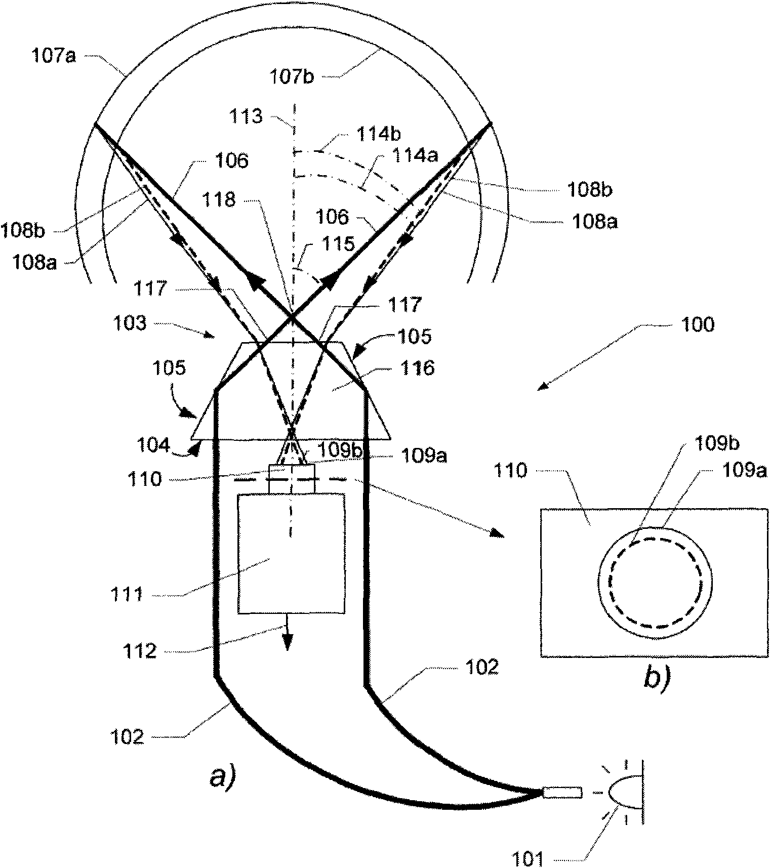
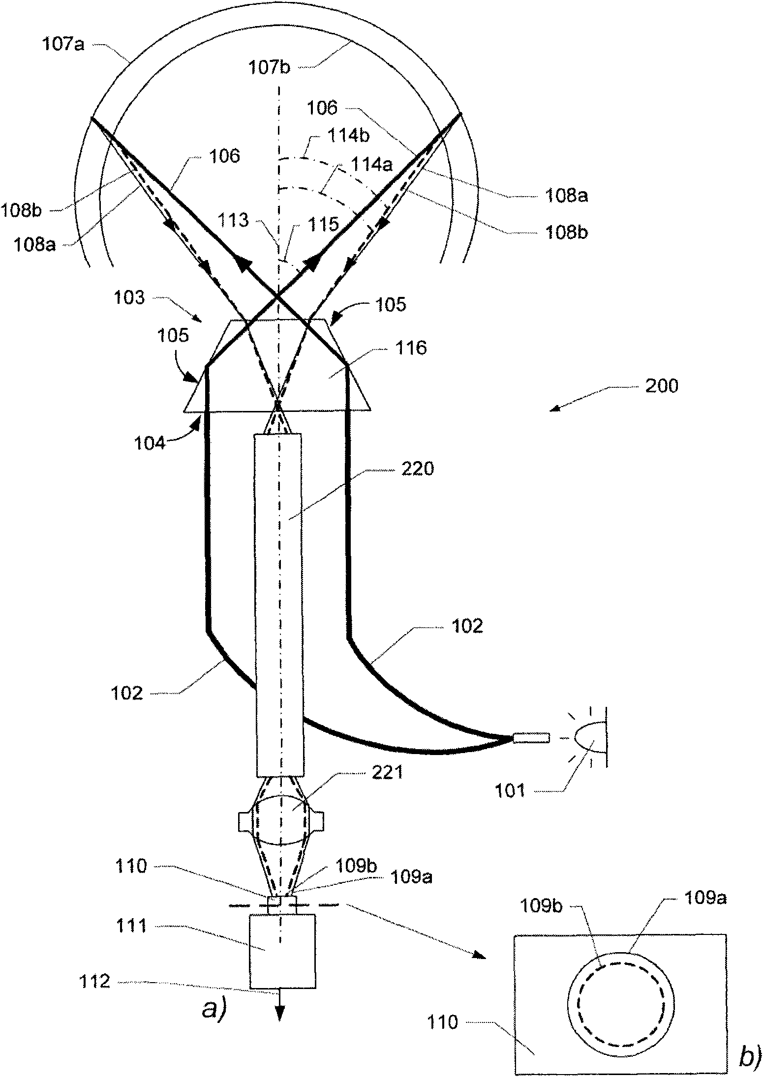
[0038] figure 1 a shows a schematic diagram of an example of a device for obtaining geometric data of the inner surface of a cavity. The device, generally designated 100, includes a distal end 103 comprising optical components for emitting and receiving light, a light source 101 and an optical waveguide 102 for directing light from the light source 101 to a rear surface 104 of an optical system 116. system 116. Optical system 116 may include one or more lenses and / or one or more reflective surfaces 105 for directing light from optical waveguide 102 as one or more beams of light 106 to inner surfaces 107a, 107b of the cavity.

[0039] The light beam 106 is emitted at an acute angle 115 relative to the optical axis 113 of the optical system 116, which also determines the insertion direction of the distal end 103 into the cavity. The light beam 106 emerges from a corresponding exit position 117 radially offset from the optical axis. Furthermore, the exit location 117 and the l...


PUM


Abstract

Disclosed is an apparatus for obtaining geometrical data relating to an internal surface of a cavity. The apparatus comprises a probe having an end portion insertable into the cavity in a direction of insertion, radiation directing means for directing electromagnetic radiation from the end portion to at least one location on the internal surface to cause the radiation to be reflected from said location, detection means for detecting the reflected radiation from the at least one location, and means for determining from the detected radiation a distance between the probe and the internal surface in a direction having at least a transverse component relative to the direction of insertion. The radiation directing means is adapted to direct the radiation at an acute angle relative to the direction of insertion.

Description

technical field [0001] The present invention relates to methods and apparatus for obtaining geometrical data of the inner surfaces of cavities such as human ears and ear canals. Background technique [0002] Interesting applications of the aforementioned methods and devices include generating data maps of the inner surface of the ear and ear canal such that three-dimensional data or digital models of the inner surface of the ear and ear canal can be obtained. Such a three-dimensional model can be used to produce housings that have the exact shape of the ear canal and can form the basis of in-the-ear (ITE) or deep-in-the-canal (CIC) hearing aids. Likewise, ear molds or shells for other purposes such as hearing protection or for headphones can be produced in this data model. The housing can be produced in different ways based on the data model, such as by recently developed rapid prototyping methods, stereolithography (SLA) or by well-known machining, for example in computer ...

Claims


Application Information

Patent Timeline
Patent Type & Authority Patents(China)
IPC IPC(8): A61B1/227A61B5/107
CPCA61B1/227A61B5/1076G01B11/24
Inventor P·福厄兹J·瑟高
Owner OTICON
Learn More