Tube expander

A tube expander and tube expansion technology, which is applied to heat exchange equipment and other directions, can solve problems such as troublesomeness and low alignment accuracy, and achieve the effects of high adjustment accuracy, fast adjustment speed and simple structure.

Active Publication Date: 2010-06-16
OMS MASCH CO LTD
View PDF1 Cites 23 Cited by
  • Summary
  • Abstract
  • Description
  • Claims
  • Application Information

AI Technical Summary

Problems solved by technology

However, when the expansion rod of this type of tube expander needs to be adjusted to align with the hole of the processing element, all the devices on the main frame must be moved. It will be troublesome to move such a heavy device, and the alignment accuracy is not very high.

Method used


Image

  • Tube expander
  • Tube expander
  • Tube expander

Examples


Embodiment Construction

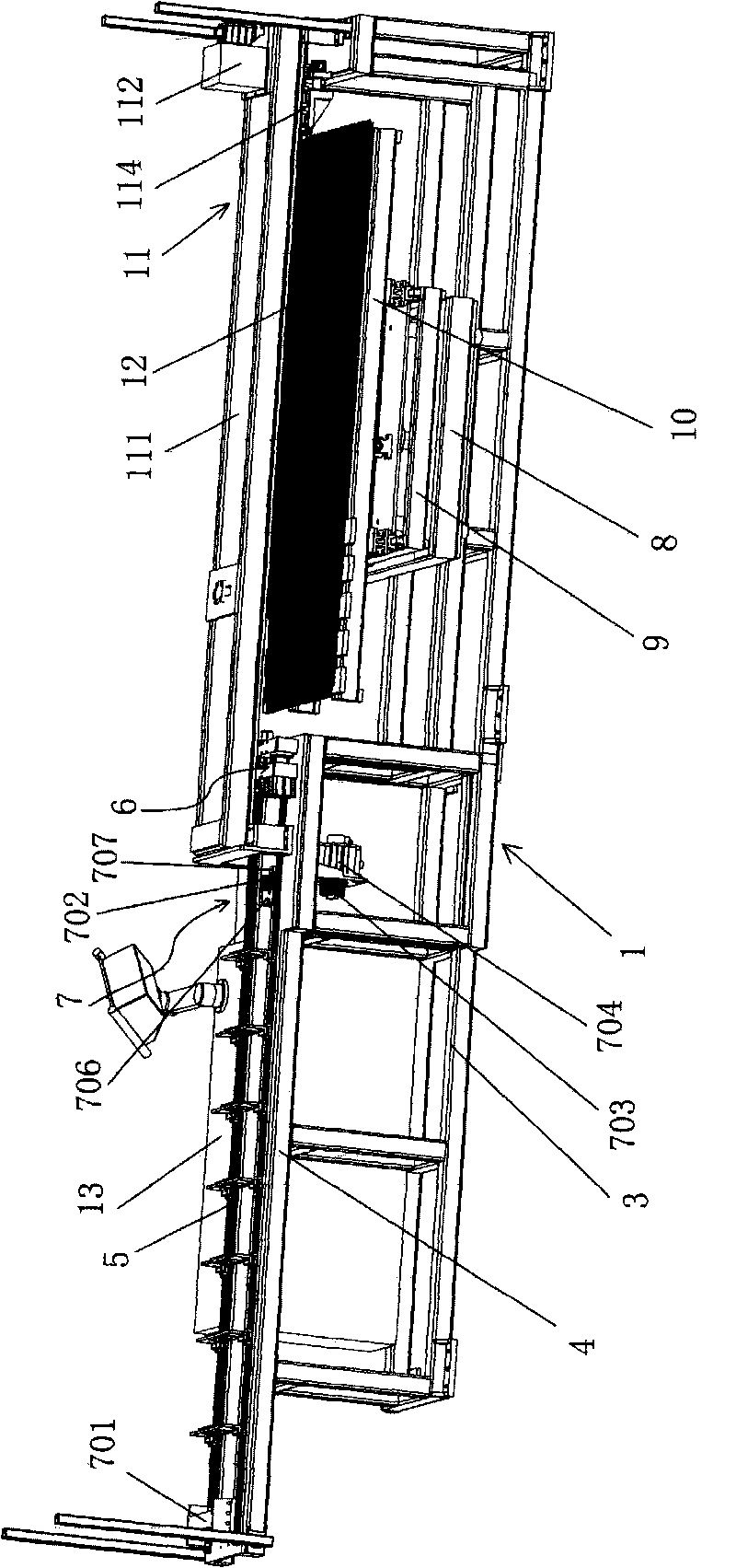
[0023] tube expander, such as figure 1 As shown, it is used to expand the metal tube of the heat exchanger 12 so that it is closely combined with the heat exchange fins to achieve a good heat conduction effect. The tube expander includes a body 1 and a control system 13 connected to the body 1, and the control system 13 is used to control the action of the whole tube expander.

[0024] Such as figure 1 , 5 As shown in . 5. The expansion rod 5 is a slender rod, and the end of the expansion rod 5 close to the clamping device 6 is provided with an expansion ball head. One end of the main frame 4 close to the workbench 2 is provided with a clamping device 6 , and the other end is provided with a push mechanism 7 for pushing the expansion rod 5 to slide. The clamping device 6 is provided with a plurality of expansion collets 604 through which the expansion rod 5 can pass.

[0025] Such as Figure 5 , 6 As shown, the pushing mechanism 7 includes a movable push plate 701 conne...


PUM


Abstract

The invention discloses a tube expander, which comprises a machine body. The main points of the technical scheme include: the machine body comprises an underframe; the underframe is provided with a mainframe; the mainframe is provided with a plurality of expanding rods which can slide on the mainframe back and forth; and one end of the mainframe is provided with a clamping device which can clamp the expanding rods, while the other end is provided with a pushing mechanism which can push the expanding rods to slide. The tube expander is characterized in that: a subframe is arranged on the underframe and on the right side of the mainframe; the subframe is provided with a lifting frame and a first driving part which can push the lifting frame to move up and down; the lifting frame is provided with a guide rail; a pipe-fitting mounting frame, which can mount pipe fittings, is loaded on the guide rail; and the lifting frame is provided with a second driving part which can push the pipe-fitting mounting frame to move forward and backward. The tube expander has the advantages of simple structure, convenient operation and high adjusting accuracy.

Description

【Technical field】 [0001] The present invention relates to a tube expander. 【Background technique】 [0002] In the production process of the heat exchanger, it is necessary to closely combine the metal tube and the fins fitted on it, so as to ensure good heat transfer and conduction, and it is light in weight and has a long service life. The method that people adopt at present is to adopt manually to insert the expansion bar with ball head into metal tube to expand metal tube, then extract expansion bar, can only expand one tube at a time, labor intensity is big and production efficiency is low. And it is very difficult to expand the metal tubes of large-scale heat exchangers, and there is an urgent need for a tube expander that can have multiple metal tubes at one time and is convenient for expanding the metal tubes of large-scale heat exchangers to be used in the production of heat exchangers. [0003] For this situation, the applicant applied for a tube expander for tube ...

Claims


Application Information

Patent Timeline
Patent Type & Authority Applications(China)
IPC IPC(8): B21D39/14B21D53/08
Inventor 肖世文
Owner OMS MASCH CO LTD
Why Eureka
Try Eureka