
Manufacturing method of light guide plate and mould used by same

A manufacturing method and technology of light guide plates, which are applied in the direction of manufacturing tools, other household appliances, household appliances, etc., can solve the problems of limited size of processed boards, high labor costs, and easy scattering of ink, so as to save labor costs, Improvement of production efficiency and many beneficial effects

Inactive Publication Date: 2010-06-16
江俊慧
View PDF0 Cites 10 Cited by
  • Summary
  • Abstract
  • Description
  • Claims
  • Application Information

AI Technical Summary

Problems solved by technology

[0002] The current production of light guide plate parts is to use a screen printing method to print ink patterns on the board parts. Because the ink is easy to scatter, it will be uneven and easy to fall off, making it difficult to control the quality. The printing step is applied after forming, so the labor cost is high
[0003] In addition, the mold core injection molding method is to first preset the pattern on the inner surface of the metal mold cavity by etching, and then inject the plastic into the mold cavity for molding. Due to uneven stress, the board will have bubbles or deformation, and the mold core injection molding The mold of the traditional method, the size of the processed plate is limited, and it is impossible to produce large-area plates, and each plate required by different patterns requires a metal mold with a high preparation cost
[0004] In addition, on the glass mold, a preset pattern is formed by etching, and then the plastic is poured into the mold to form a plate. First, it is necessary to select the etched position for exposure, and then use the etching method to perform exposure according to the exposed pattern. Corrosion, but the corrosion cannot be precisely and uniformly controlled, the success rate is very low and it can only be produced in a single piece, which is not in line with the production efficiency. Moreover, the glass mold mentioned above is corroded by strong acid, and the danger of the production process is derived.

Method used


Image

  • Manufacturing method of light guide plate and mould used by same
  • Manufacturing method of light guide plate and mould used by same
  • Manufacturing method of light guide plate and mould used by same

Examples


Embodiment Construction

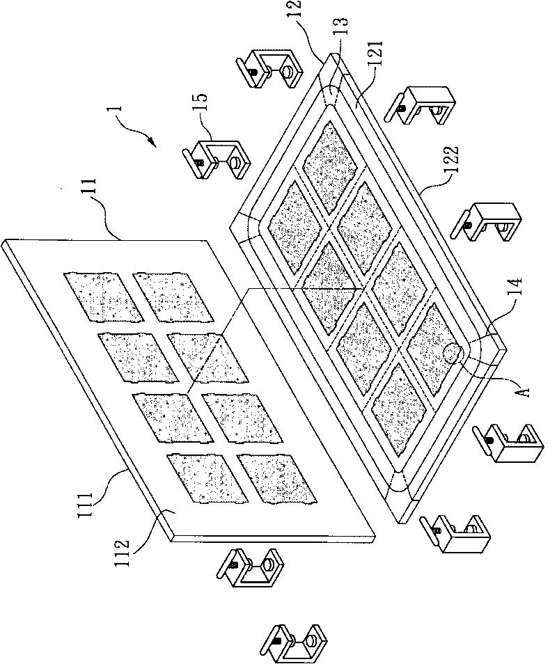
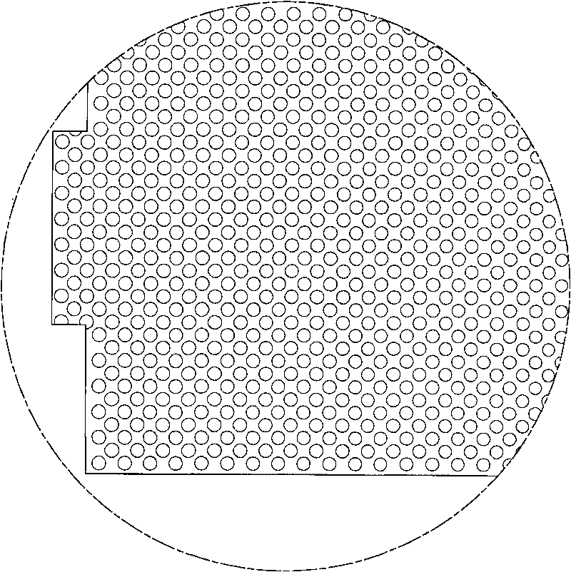
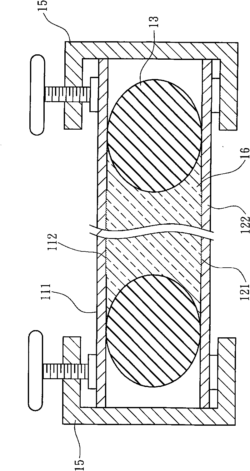
[0061] see Figure 1 to Figure 3 What is shown in the figure is the selected embodiment structure of the present invention, which is for illustration only, and is not limited by this structure in the patent application.

[0062] The following is an example description of the manufacturing method of the light guide plate of the present invention and the mold used therefor, which includes:

[0063]A mold 1 , the mold 1 includes: an upper mold 11 , a lower mold 12 , an elastic element 13 , a fixing element 14 and a clamping element 15 . The upper mold 11 has an upper surface 111 and a lower surface 112, and the lower mold 12 has an upper surface 121 and a lower surface 122, and the upper mold 11 and the lower mold 12 are made of glass material.

[0064] At least one of the lower surface 112 of the upper mold 11 and the upper surface 121 of the lower mold 12 is processed with a preset pattern by means of sandblasting technology, wherein the sand material used in the sandblasting ...


PUM


Abstract

The invention relates to a manufacturing method of a light guide plate and a mould used by the same. The mould is a glass mould which comprises an upper mould, a lower mould, an elastic element, a fixed element and a clamping element. The manufacturing method of the light guide plate comprises the following steps of: firstly, sticking numerical plastic films with pre-made patterns to the upper mould and the lower mould; secondly, processing the glass mould by adopting a sand spraying technology according to the high-speed particle collision principle; and finally pouring the blended and filtered sizing; after pouring, fastening the upper mould and the lower mould in the glass mould subject to sand spraying by using the clamping element; carrying out curing and polymerization reaction; and then carrying out mould removable, cutting, quality control, package and subsequent manufacturing procedures to finally finish the manufacture of various light guide plates.

Description

technical field [0001] The invention relates to a method for manufacturing a light guide plate, and also relates to a mold required for manufacturing the light guide plate. Background technique [0002] The current production of light guide plate parts is to use a screen printing method to print ink patterns on the board parts. Because the ink is easy to scatter, it will be uneven and easy to fall off, making it difficult to control the quality. The printing step is applied after forming, so the labor cost is high. [0003] In addition, the mold core injection molding method is to first preset the pattern on the inner surface of the metal mold cavity by etching, and then inject the plastic into the mold cavity for molding. Due to uneven stress, the board will have bubbles or deformation, and the mold core injection molding The mold of this method is limited in the size of the processed plate, and cannot produce large-area plates, and each plate required by a different patte...

Claims


Application Information

Patent Timeline
IPC IPC(8): B29C33/42B29C33/38B29C33/20B29C39/26B29C39/02B29C39/38B24C11/00B24C1/00B29L11/00B29K33/04
Inventor 江俊慧
Owner 江俊慧
Learn More