Supercharge Your Innovation With Domain-Expert AI Agents!

Drying apparatus, recording apparatus and method for drying target

A drying device and drying method technology, applied in printing devices, inking devices, printing, etc., can solve the problems of high speed, inability to increase wind speed, inability to dry ink, etc.

Inactive Publication Date: 2010-06-16
SEIKO EPSON CORP
View PDF1 Cites 4 Cited by
  • Summary
  • Abstract
  • Description
  • Claims
  • Application Information

AI Technical Summary

Problems solved by technology

Therefore, it is impossible to increase the speed of the blown air for the target, and furthermore, it is impossible to increase the drying speed of the ink proportional to the wind speed.

Method used


Image

  • Drying apparatus, recording apparatus and method for drying target
  • Drying apparatus, recording apparatus and method for drying target
  • Drying apparatus, recording apparatus and method for drying target

Examples


no. 1 approach

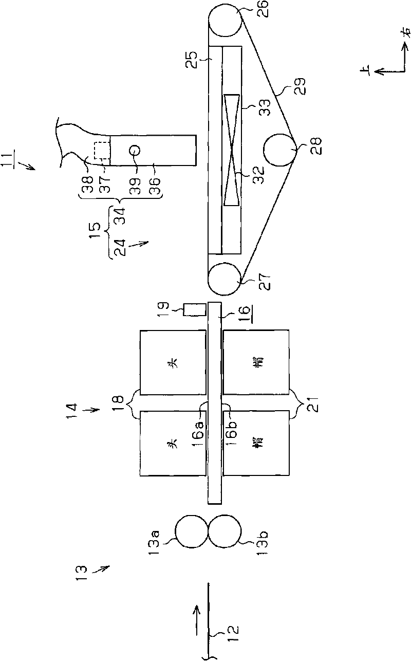
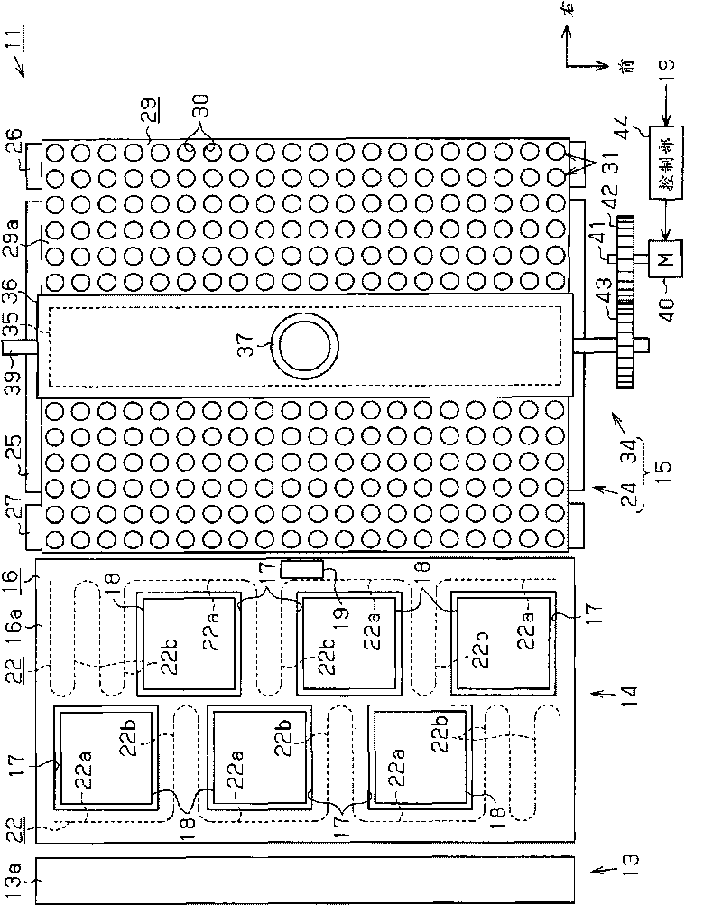
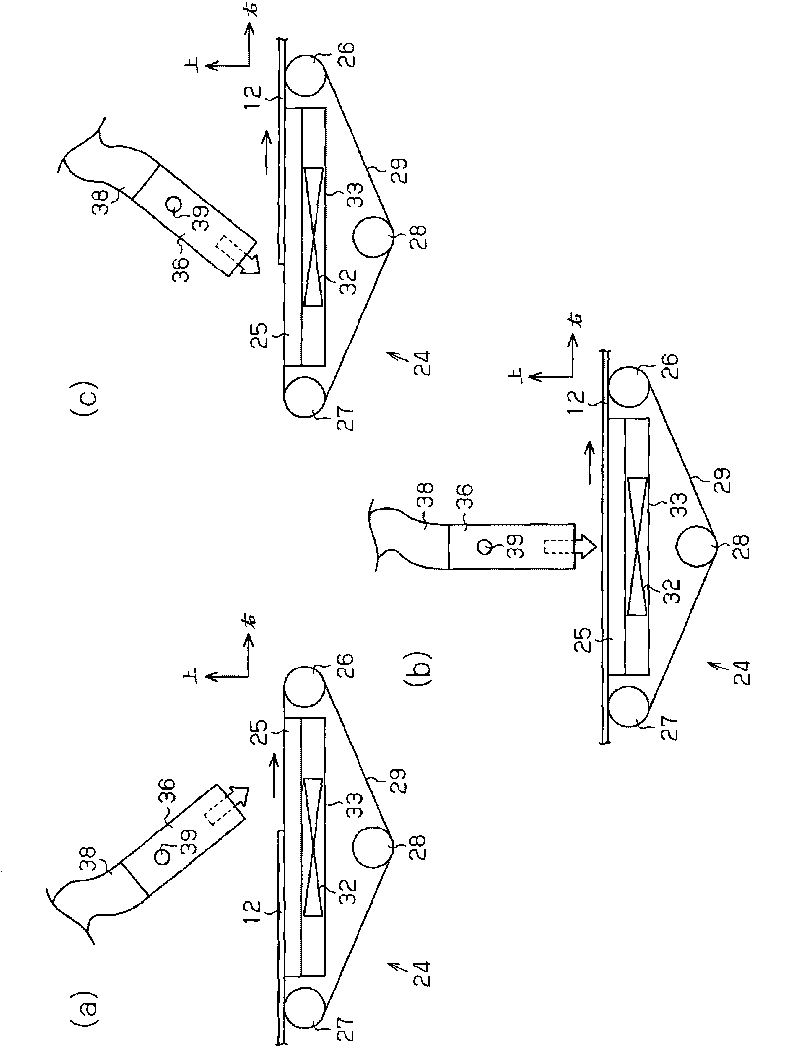
[0029] Below, according to Figure 1 ~ Figure 3 A first embodiment in which the recording device of the present invention is embodied as an inkjet printer (hereinafter referred to as "printer") will be described. In addition, in the following description, when referring to "front-rear direction", "left-right direction", and "up-and-down direction", it means figure 1 and figure 2 The direction indicated by the arrow in is the direction shown based on the reference.

[0030] like figure 1 and figure 2As shown, a printer 11 as a recording device includes: a preheating device 13 for heating a target paper 12 in the form of a single sheet supplied from a paper feeding tray not shown in the figure; The heating device 13 performs printing on the paper 12 heated; and the drying device 15 dries the paper 12 to fix the printing. Furthermore, the paper 12 dried by the drying device 15 is discharged to a discharge tray not shown.

[0031] The preheating device 13 is provided with ...

no. 2 approach

[0066] Below, according to Figure 4 A second embodiment of the present invention will be described. In addition, since the second embodiment differs from the first embodiment only in that the hot air unit is changed, and other structures are the same, the same components are given the same reference numerals and detailed repeated descriptions are omitted.

[0067] In the hot air unit 45 , three air blowing fans 46 to 48 and unillustrated heaters are provided in separate air blowing sections 49 to 51 , respectively. In addition, the left and right walls of each of the air blowers 49 to 51 extend toward the paper 12 conveyed by the conveyance unit (not shown), and are composed of four guide plates 52 to 55 provided across the width direction (front-rear direction) of the paper 12 . .

[0068] Furthermore, both front and rear walls of the air blowers 49 to 51 are formed by a front plate and a rear plate 59 (not shown) having the same dimensions as the guide plates 52 to 55 in ...

no. 3 approach

[0078] Below, according to Figure 5 A third embodiment of the present invention will be described. In addition, the third embodiment differs from the above-described embodiments only in that the hot air unit is changed, and other structures are the same. Therefore, the same components are given the same reference numerals and detailed repeated descriptions are omitted.

[0079] like Figure 5 As shown, in the hot air unit 60 , the first drying unit 61 serving as the first blowing mechanism and the second drying unit 62 serving as the second blowing mechanism, which are trapezoidal in plan view, are juxtaposed so as to be adjacent to each other in a part along the left-right direction. They are arranged in the front-rear direction and fixed to the rectangular plate 63 .

[0080] That is, the hot air unit 60 is provided with at least one (in this embodiment, three) first drying parts 61 along the front-rear direction, and the dimensions in the front-rear direction at the left...


PUM


Abstract

A drying apparatus includes a transport unit that transports a target in a form of a cut sheet, on which a recording process has been performed through the attachment of liquid, from an upstream side to a downstream side of a transport direction. A drying unit performs a drying process on the transported target by blowing air toward a liquid attachment surface of the target. The drying unit is provided with a blowing port which allows air to blow toward an end portion of the target at the downstream side of the transport direction in a first direction from the upstream side to the downstream side of the transport direction, and allows air to blow toward an end portion of the target at the upstream side of the transport direction in a second direction from the downstream side to the upstream side of the transport direction.

Description

technical field [0001] The present invention relates to a drying device that promotes the drying of liquid adhering to a recorded target to fix recording on the target, a recording device equipped with such a drying device, and a method of drying a target. Background technique [0002] Conventionally, an inkjet printer (hereinafter referred to as a "printer") is known as a recording device that performs recording by adhering a liquid to a target. This printer performs printing (recording) on ​​a target sheet of paper by ejecting ink (liquid) supplied to the recording head from nozzles formed on the recording head. [0003] Among such printers, recently, as described in Patent Document 1, for example, there is a printer equipped with a drying device in order to promote drying of ink adhering to paper. That is, the drying device dries the ink by blowing hot air to the paper on which the ink is attached. [0004] [Patent Document 1] Japanese Patent Laid-Open No. 2003-54796 ...

Claims


Application Information

Patent Timeline
Patent Type & Authority Applications(China)
IPC IPC(8): B41J11/00B41J2/00
CPCB41J2/155B41J11/002B41J2202/20B41J11/00244B41J11/00222
Inventor 原启志新川修
Owner SEIKO EPSON CORP
Features
  • R&D
  • Intellectual Property
  • Life Sciences
  • Materials
  • Tech Scout
  • Unparalleled Data Quality
  • Higher Quality Content
  • 60% Fewer Hallucinations
Learn More