Hydraulic drag device

A kind of resistor and hydraulic technology, applied in the direction of ship parts, ships, steering gear, etc., can solve the problems of difficult to control, difficult to effectively control the size of the resistance, unsatisfactory deceleration effect, etc.

Inactive Publication Date: 2010-06-16
王惠 +1
View PDF0 Cites 2 Cited by
  • Summary
  • Abstract
  • Description
  • Claims
  • Application Information

AI Technical Summary

Problems solved by technology

It is difficult to effectively control the resistance of the hydraulic drag booster with the above structure in the application process, and it is difficult to control it according to the water entry depth of the drag booster and the speed of the ship
For different ships and other water sports objects, the deceleration effect is often not ideal

Method used


Image

  • Hydraulic drag device
  • Hydraulic drag device
  • Hydraulic drag device

Examples


Embodiment Construction

[0022] The hydraulic drag booster of the present invention will be further described in detail below in conjunction with the accompanying drawings and specific embodiments, but this should not limit the protection scope of the present invention.

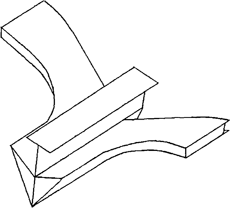
[0023] please see figure 1 , figure 1 It is a schematic diagram of the overall structure of the hydraulic drag booster of the present invention. As can be seen from the figure, the structure of the hydraulic drag booster of the present invention is a symmetrical flying bird shape as a whole, including a main body and two wings. The front end of the main body is a water inlet, and the rear ends of the two wings are water outlets. The water inlet A smooth cavity communicating with the water outlet is provided.

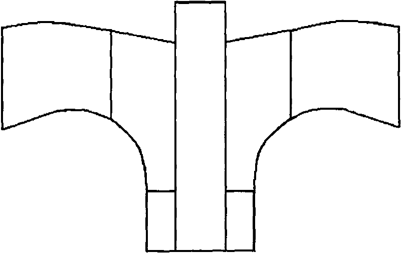
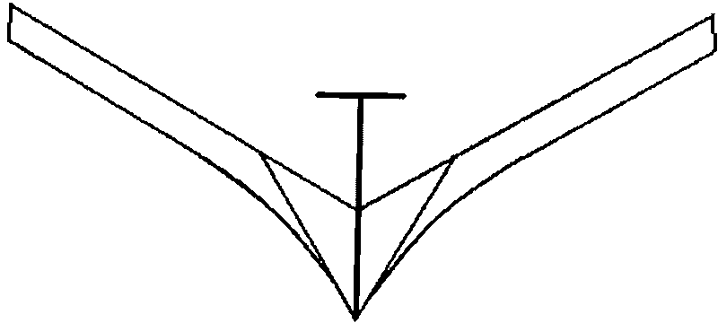
[0024] Depend on figure 2 and image 3 The structure of the hydraulic drag booster of the present invention can be further seen. figure 2 It is a top view structure schematic diagram of the hydraulic drag booster of the ...


PUM


Abstract

The invention relates to a hydraulic drag device which is structurally like a symmetric flying bird as a whole. The hydraulic drag device comprises a body and two wings. The front end of the body is provided with a water inlet. The rear ends of the two wings are provided with water outlets. Smooth cavities which are communicated with each other are arranged between the water inlet and the water outlets. The hydraulic drag device can be better suitable for different flow states. When flowing into a supercharger cavity, the water ascends along the wall of the inner cavity, thereby reaching dynamic equilibrium. The hydraulic drag device has good effect on removing the pressure of water and can be suitable for the requirements of different occasions.

Description

technical field [0001] The invention relates to a deceleration machine, in particular to a hydraulic drag booster which utilizes the resistance of water to realize the deceleration of a high-speed moving object. Background technique [0002] A hydraulic drag booster is a device that uses the resistance of water to slow down a high-speed moving object. In practical applications, the device is fixed on a high-speed moving object and moves together with the high-speed object. When deceleration is required, the device is immersed in water, and the resistance provided is controlled by adjusting the depth of immersion. The movement of the hydraulic drag booster on the water surface is essentially a two-phase (gas phase and water) flow, and the free liquid surface is the interface between water and air. [0003] The hydrodynamic characteristics of the motion of objects near the free surface have been widely concerned by people, the most important thing is how to control the speed ...

Claims


Application Information

Patent Timeline
Patent Type & Authority Applications(China)
IPC IPC(8): B63H25/00B63H25/50
Inventor 王惠罗俊
Owner 王惠
Why Eureka
Try Eureka