Ultrasonic gas static electric spindle

A pneumatic and electric spindle technology, applied in the direction of large fixed members, metal processing machinery parts, metal processing equipment, etc., can solve the problem of reducing the life of the spindle bearing and the accuracy of the spindle, restricting the promotion and application of ultrasonic waves, and narrowing the range of tool options, etc. Problems, to achieve outstanding performance, huge economic benefits and promotion and application prospects, the effect of a wide range of precision processing industries

Pending Publication Date: 2020-01-17
LUOYANG CHUANSHUN MACHINERY EQUIP
View PDF0 Cites 0 Cited by
  • Summary
  • Abstract
  • Description
  • Claims
  • Application Information

AI Technical Summary

Problems solved by technology

[0003] However, the ultrasonic tool handle device in the prior art has the problems of many parts and complex structure, and the tool handle must be dedicated, resulting in a narrow range of tool options
In the application process, ultrasonic vibration will greatly reduce the life of the spindle bearing and the accuracy of the spindle, resulting in a large amount of maintenance, high cost of use, etc., which greatly restricts the promotion and application of ultrasonic in the processing field

Method used


Image

  • Ultrasonic gas static electric spindle
  • Ultrasonic gas static electric spindle

Examples


Embodiment Construction

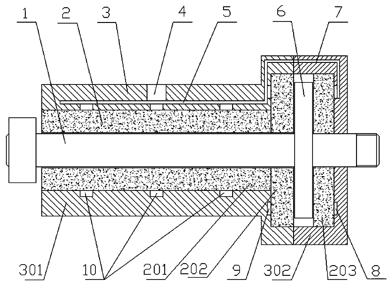
[0018] like figure 1 As shown, an ultrasonic aerostatic piezoelectric spindle of the present invention includes an air bearing shell 3 , an air bearing body 2 and a rotating shaft core 1 that are sleeved in sequence from outside to inside. The left end of the rotating shaft core 1 protrudes from the left side of the air bearing body 2 and is provided with a pulley, so as to be connected with the motor through the pulley transmission mechanism, and the rotating shaft core 1 is driven by the motor to rotate. The right end of the rotating shaft core 1 protrudes from the right side of the air bearing body 2 and is provided with an external thread, so as to be convenient for connecting a tool handle, a tool, a tool shank, a grinding wheel shank or a matching fixture. A circular thrust plate 6 is fixed concentrically near the right end of the rotating shaft core 1 , and the high frequency vibration of the rotating shaft core 1 along the axial direction of the air bearing body 2 is r...


PUM


Abstract

The invention relates to a machine tool cutting auxiliary device, in particular to an ultrasonic gas static electric spindle. The ultrasonic gas static electric spindle comprises an air bearing shell,an air bearing body and a rotary shaft core, wherein the air bearing shell, the air bearing body and the rotary shaft core are sequentially sleeved from outside to inside. The air bearing body is fixed into the air bearing shell, the rotary shaft core is rotationally arranged in the air bearing body, and the rotary shaft core can move in the axial direction of the air bearing body. A thrust plateis fixedly arranged on the rotary shaft core. The air bearing body comprises a radial bearing body used for cooperating with the periphery of the rotary shaft core, an axial rear thrust bearing bodyused for cooperating with one side of the thrust plate and an axial front thrust bearing body used for cooperating with the other side of the thrust plate. The radial bearing body, the axial rear thrust bearing body and the axial front thrust bearing body are made of nano carbon fiber materials with uniform open air holes, and the densities of the open air holes are different. The ultrasonic gas static electric spindle is simple in structure and simple in control manner, can be in butt joint with a universal tool clamp, and has great economic benefits and application and popularization prospects.

Description

technical field [0001] The invention relates to a cutting auxiliary device of a machine tool, in particular to an ultrasonic gas-static electric spindle. Background technique [0002] At present, the common form of traditional ultrasonic in machine tool equipment is ultrasonic tool handle device, including: ultrasonic power supply, transducer, horn and tool handle and other subsystems. The electrical energy is converted into the mechanical energy of the tool holder vibrating in the axial direction through the transducer and the horn, so that the tool on the tool holder can perform high-frequency vibratory reciprocating feed grinding (turning) on ​​the workpiece to achieve special grinding. (turning) cutting effect. [0003] However, the ultrasonic tool handle device in the prior art has the problems of many components and complex structure, and the tool handle must be dedicated, resulting in a narrow selection range of tools. In the application process, ultrasonic vibratio...

Claims


Application Information

Patent Timeline
Patent Type & Authority Applications(China)
IPC IPC(8): B23B19/02
CPCB23Q1/70
Inventor 魏传波王强志
Owner LUOYANG CHUANSHUN MACHINERY EQUIP
Why Eureka
Try Eureka