Bionic human nasal gas chamber

A gas chamber, bionic human technology, applied in the direction of instruments, measuring devices, scientific instruments, etc., to achieve the effect of easy promotion and use, low cost, and easy installation

Inactive Publication Date: 2010-06-16
JILIN UNIV
View PDF0 Cites 10 Cited by
  • Summary
  • Abstract
  • Description
  • Claims
  • Application Information

AI Technical Summary

Problems solved by technology

This has also led to most current research on electronic nose systems focusing on neural network algorithms and s

Method used


Image

  • Bionic human nasal gas chamber
  • Bionic human nasal gas chamber
  • Bionic human nasal gas chamber

Examples


Embodiment Construction

[0016] The specific content and implementation process of the present invention will be further described below in conjunction with the embodiments shown in the accompanying drawings.

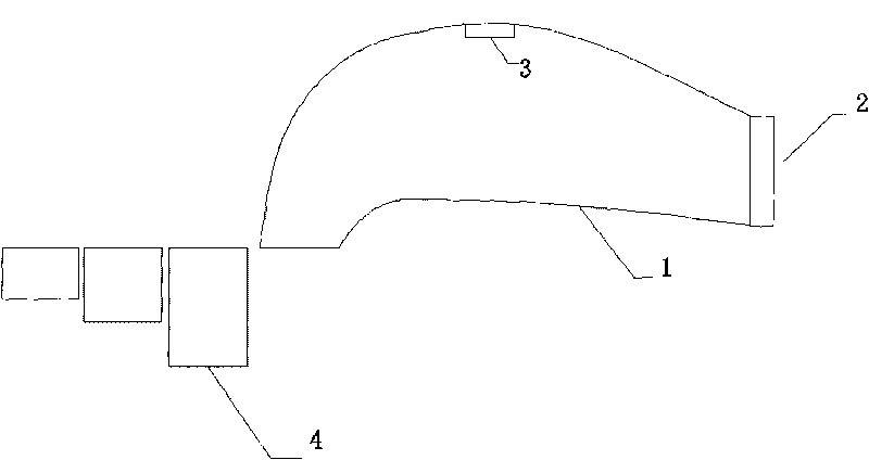
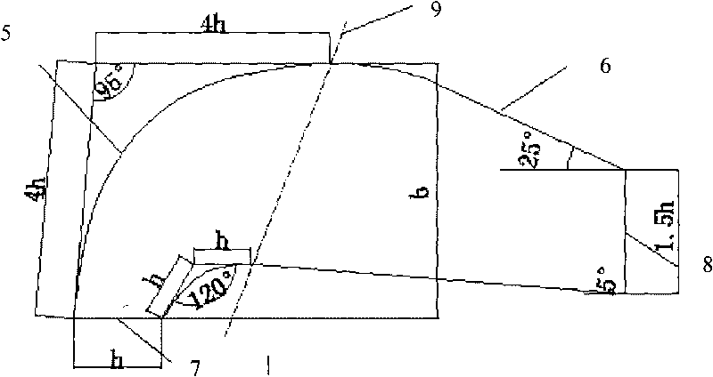
[0017] refer to figure 1 , 2 , the present invention includes a gas chamber 1, a blower fan 2, a sensor 3 and a measured gas collection interface 4, the sensor 3 is arranged above the inside of the gas chamber 1, the measured gas collection interface 4 is installed at the air inlet end of the gas chamber 1, and installed in the gas chamber The fan 2 at the tail of 1 provides power for the flow of the measured gas. The gas chamber 1 is designed to imitate the structure of the human nose, and has a human nasal cavity structure, which includes a transition section 5 and an outlet section 6. The upper and lower interior of the transition section 5 The cavities are all arcs, the upper and lower inner cavities of the outlet section are straight lines at 24° to 26°, 4.5° to 5.5° with the air inlet 7,...


PUM


Abstract

The invention relates to a bionic human nasal gas chamber, which belongs to the field of mechanical engineering. The chamber comprises that: a sensor (3) is arranged above the inside of a gas cavity (1); a detected-gas collection interface (4) is arranged at the air inlet end of the gas cavity (1); a fan (2) arranged on the tail part of the gas cavity (1) provides power for the flowing of detected gas; the gas cavity (1) has a bionic human nasal inner cavity structure comprising a transition section (5) and an outlet section (6); an upper inner cavity and a lower inner cavity of the transition section (5) are both arc lines; the upper inner cavity and the lower inner cavity of the outlet section are both straight lines at an angle of 24 to 26 degrees or 4.5 to 5.5 degrees to an inlet (7); and two straight lines extend towards the direction of the inlet (7) and intersect with the arc lines of the upper inner cavity and the lower inner cavity of the transition section (5) of the gas cavity respectively. The gas chamber has the function of acquiring odor information of wine, meat and vegetables, and has the advantages of simple structure, convenience for installation, low cost and easy popularization and application.

Description

technical field [0001] The bionic human nose gas chamber of the invention relates to a gas chamber of an electronic nose system and belongs to the field of mechanical engineering. Background technique [0002] When organisms inhale, odor molecules reach the olfactory cells through convection and diffusion, thereby producing olfaction. This process involves several influencing factors, such as nasal cavity structure, airflow velocity field, diffusivity and adsorption of odor molecules in the air and mucous membrane layer sex etc. Researchers have proposed many theoretical models from different angles, most of which focus on the diffusion and absorption of odor molecules in the mucosal layer and the reaction process of olfactory cells, and few involve the connection between nasal cavity structure and odor molecules during transmission. This has also led to the fact that most of the current research on electronic nose systems focuses on neural network algorithms and sensor arr...

Claims


Application Information

Patent Timeline
IPC IPC(8): G01N33/00G01N1/24
Inventor 佟金常志勇陈东辉佟月英吴钟晶马云海周江孙霁宇贾洪雷陈玉香阎久林
Owner JILIN UNIV
Why Eureka
Try Eureka