Automobile/robot foot structure

A technology for robots and automobiles, applied in the field of robots, can solve the problems of difficult to place inside the legs, large size, difficult to anthropomorphize robots, etc., and achieve the effect of stable state

Active Publication Date: 2010-06-23
SHANGHAI JINGYI ELECTRICAL APPARATUS FACTORY CO LTD +1
View PDF0 Cites 13 Cited by
  • Summary
  • Abstract
  • Description
  • Claims
  • Application Information

AI Technical Summary

Problems solved by technology

This kind of structure is bulky and difficult to place inside the legs. It is usually placed outside the legs

Method used


Image

  • Automobile/robot foot structure
  • Automobile/robot foot structure
  • Automobile/robot foot structure

Examples


Embodiment Construction

[0015] The present invention will be further described below in conjunction with accompanying drawing.

[0016] The left and right feet of the foot structure of the automobile / robot of the present invention are arranged symmetrically and have the same structure. In this embodiment, the right foot is taken as an example for illustration.

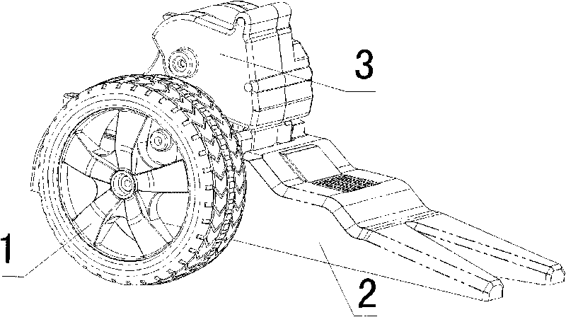
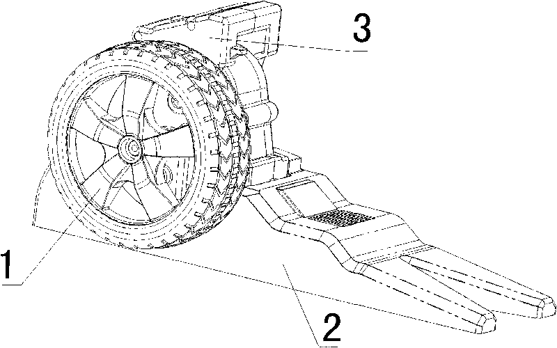
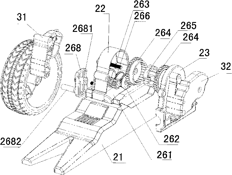
[0017] see figure 1 , figure 2 , with reference to image 3 , Figure 4 , Figure 5 , the foot structure of the automobile / robot of the present invention is rotatably connected with the legs of the robot, including a wheel 1 , a foot assembly 2 and a leg-foot connection assembly 3 . The wheel 1 is arranged on the outside of the foot assembly 2 . When the wheel 1 rotates downwards to be lower than the soles of the feet, and the leg-foot connecting assembly rotates downwards to the horizontal position, the foot structure realizes the deformation from the robot to the car (such as figure 1 shown). When the wheel 1 rotates upwards to be h...


PUM


Abstract

The present invention provides an automobile/robot foot structure. The foot structure comprises wheels, a foot assembly and a foot connecting assembly. The foot assembly comprises one group of power drive mechanism. The wheels are arranged outside the foot assembly, and are in drive connection with the power drive mechanism. The wheels can be driven by the power drive mechanism to rotate upward to positions higher than the foot bottom, and the transformation from an automobile to a robot is realized. Otherwise, the wheels can be driven by the power drive mechanism to rotate downward to positions lower than the foot bottom, and the transformation from the robot to the automobile is realized. The foot connecting assembly is covered on the foot assembly, and is in drive connection with the power drive mechanism. The foot connecting assembly can be driven by the power drive mechanism to rotate upward to a vertical position for realizing the transformation from the automobile to the robot. Otherwise, the foot connecting assembly can be driven by the power drive mechanism to rotate downward to a horizontal position for realizing the transformation from the robot to the automobile. Only one motor is arranged in each foot structure, and the wheels and the foot connecting assembly can be simultaneously driven by the motors to rotate. The present invention has the advantages of simple and compact structure, accurate action and stable properties.

Description

technical field [0001] The invention relates to a robot, in particular to a car / robot foot structure. Background technique [0002] In the field of robotics, a variety of robots and robot structures have emerged, but there is no car / robot that can transform between cars and walking robots. Robot foot structures vary widely, one of which is a parallelogram linkage structure. This kind of structure is bulky, it is difficult to place it inside the leg, and it is usually placed outside the leg independently. For a robot with a relatively simple structure, it is difficult to be used for anthropomorphic robots. Contents of the invention [0003] The purpose of the present invention is to provide a novel automobile / robot foot structure. [0004] The technical solution of the present invention is: a foot structure of a car / robot, which is rotatably connected with the legs of the robot, including wheels, foot assemblies and leg-foot connection assemblies, and the foot assembly in...

Claims


Application Information

Patent Timeline
IPC IPC(8): B62D57/02B62D63/04
Inventor 刘光华李风波刘鼎红张重清卢慧坚徐正阳
Owner SHANGHAI JINGYI ELECTRICAL APPARATUS FACTORY CO LTD
Why Eureka
Try Eureka