
Anti-falling device of attached lifting scaffold

A technology for attaching lifting and scaffolding, which is applied to the scaffolding supported by the building structure, the building structure support, the building structure support, etc. Effect

Inactive Publication Date: 2010-06-23
CHONGQING YINGFENGSHENG MACHINERY EQUIP
View PDF1 Cites 10 Cited by
  • Summary
  • Abstract
  • Description
  • Claims
  • Application Information

AI Technical Summary

Problems solved by technology

Among them, the ratchet pawl type must be equipped with anti-falling teeth along the entire height of the scaffold, so the production cost is relatively high, while the ratchet pawl type and wedge type brake are reliable and low in cost, but the installation of the excitation device is very complicated, such as Chinese patent ZL03202949. As disclosed in 7, due to the poor operability, workers often do not use it according to the regulations during operation, making the anti-falling device useless

Method used


Image

  • Anti-falling device of attached lifting scaffold
  • Anti-falling device of attached lifting scaffold

Examples


Embodiment Construction

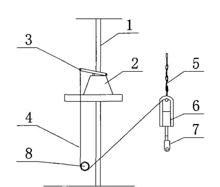
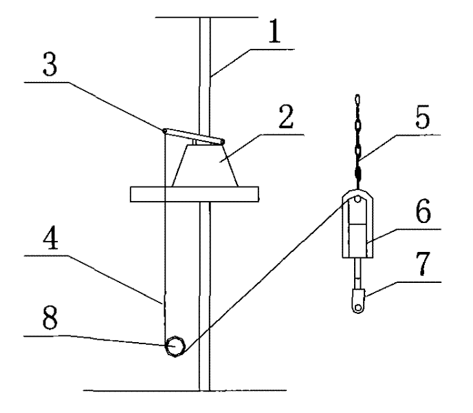
[0011] The structural principle of the fall arrester of the present invention can be referred to in the Chinese patent ZL03202949.7, and will not be repeated here. This embodiment mainly describes the excitation device.

[0012] Such as figure 1 As shown, the suspender 1 passes through the anti-fall device 2 installed on the scaffold body, the push rod 3 of the anti-fall device 2 is connected to the steel wire rope 4, and the lower end of the steel wire rope 4 bypasses the steel pipe 8 connected to the frame body with a fastener. One end is connected to the lower hook 5 of the electric hoist, the lower hook 5 of the electric hoist is hung on the upper part 6 of the lifting ring, the upper part 6 and the lower part 7 of the lifting ring can move relative to each other and a spring is provided, and the lower part 7 of the lifting ring is connected to the frame body (not marked in the figure).

[0013] For those skilled in the art, under the premise of not departing from the st...


PUM


Abstract

The invention discloses an anti-falling device of an attached lifting scaffold, which comprises a suspension rod of which the top part is connected with an attachment device of the attached lifting scaffold, and a falling protector arranged on the lower part of a main frame of the attached lifting scaffold, wherein the suspension rod passes through the falling protector to extend along the lower part of the scaffold; the falling protector comprises a body, a fixture block, a return spring and a push rod; an inclined plane slideway is arranged in the body of the falling protector; the contact surface of the fixture block which is arranged relative to the left side and the right side of the suspension rod and suspension rod is provided with braking screw threads; the fixture block is arranged in the inclined plane slideway; the return spring is arranged between the bottom of the fixture block and a lower end cover of the body; and the push rod is hinged on an upper end cover of the body, and a position, corresponding to the fixture block, of the upper end cover is provided with an ejector rod. The anti-falling device is characterized by further comprising an excitation device which comprises a guy cable of which one end is connected with the push rod, and a steering apparatus arranged on the lower part of a frame body, wherein the guy cable rounds the steering apparatus, and the other end of the guy cable is connected with a lower hook of an electric block of the attached lifting scaffold. The anti-falling device of the attached lifting scaffold has the advantages of being simple in structure, convenient and practical; when the electric block is stressed, the anti-falling device is in an open state, and the scaffold can be operated freely; when a chain of the electric block is fractured, the fixture block can be excited to reset quickly to ensure that the braking screw threads on the fracture block contact the suspension rod.

Description

technical field [0001] The invention relates to an anti-falling device, in particular to an anti-falling device during the operation of an attached lifting scaffold. Background technique [0002] In the existing building construction technology, attached lifting scaffolding is widely used. The lifting process is generally like this, one end of the electric hoist is fixed on the building, the other end is connected to the scaffolding frame, the electric hoist is started, and the lifting of the scaffolding body is realized through the forward and reverse rotation of the electric hoist. Due to the unbalanced load weight of each machine position and the difference in the manufacture of the electric hoist, the operation of the electric hoist may be fast or slow, especially during the operation of the scaffold, the electric hoist may fail or be attached to the building, resulting in overloading of the electric hoist, or even The chain broke, causing a fall safety accident on the ...

Claims


Application Information

Patent Timeline
IPC IPC(8): E04G3/32
Inventor 黄书凯倪富生陈吉川王学勇
Owner CHONGQING YINGFENGSHENG MACHINERY EQUIP
Learn More