Fuel pump

A fuel pump and fuel technology, applied in the direction of pumps, liquid fuel feeders, liquid fuel engines, etc., can solve the problems of reduced pump efficiency, fuel leakage, etc., and achieve the effects of inhibiting contact, inhibiting wear, and high pump efficiency

Inactive Publication Date: 2010-06-23
MITSUBISHI ELECTRIC CORP
View PDF1 Cites 4 Cited by
  • Summary
  • Abstract
  • Description
  • Claims
  • Application Information

AI Technical Summary

Problems solved by technology

If the impeller comes into contact with accumulated foreign matter, it will wear the impeller and / or the inner surface of the housing and cause fuel leakage from the pump passage, reducing the efficiency of the pump

Method used


Image

  • Fuel pump
  • Fuel pump
  • Fuel pump

Examples


Embodiment approach 1

[0020] Embodiment 1 according to the present invention will be described based on the drawings.

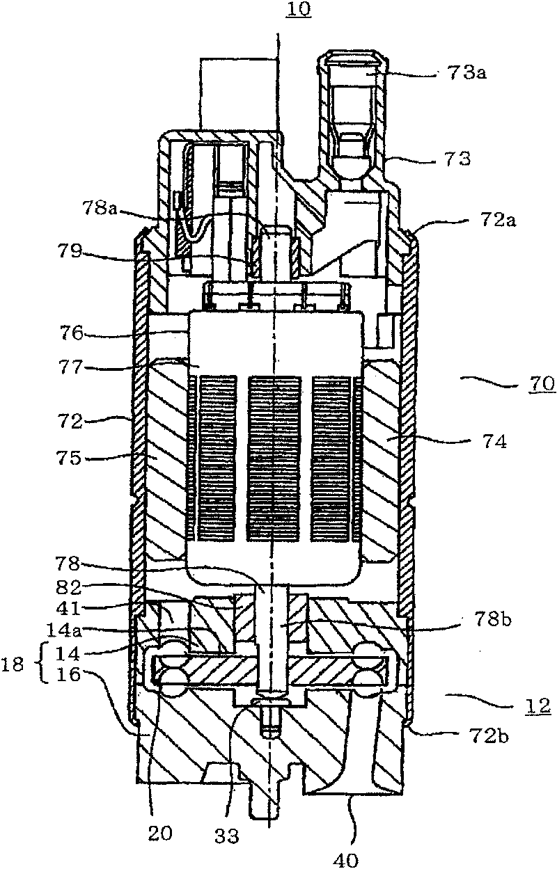
[0021] First, refer to figure 1 , illustrating the mechanical structure of the fuel pump. like figure 1 As shown, the fuel pump 10 is composed of a motor portion 70 and a pump portion 12 .

[0022] The motor unit 70 has a housing 72 , a motor cover 73 , magnets 74 and 75 , and a rotor 76 . The casing 72 is formed in a substantially cylindrical shape. The motor cover 73 passes the upper end 72a of the housing 72 (the figure 1 The top and bottom of the fuel pump 10 are crimped inwardly to be fixed on the casing 72 . A discharge port 73 a opening upward is formed in the motor cover 73 . Magnets 74 , 75 are fixed on the inner wall of housing 72 . The rotor 76 has a main body 77 (composed of laminated iron cores, coils, etc.) and a shaft 78 penetrating the main body 77 up and down. The upper end portion 78 a of the shaft 78 is rotatably mounted on the motor cover 73 via a beari...


PUM


Abstract

The present invention provides a fuel pump, capable of preventing foreign matters stacked on the outer circumference of an impeller from contacting the impeller and preventing the efficiency of the pump from being reduced. The fuel pump is provided with a roughly circular disk shaped impeller (20) rotating through a motor part (70); and a housing (18) for accepting the impeller rotatablely and provided with foreign matter discharge passageways (100, 101) on the inner surface of the housing, wherein the discharge passageways are arranged on a position facing to a region between the outer circumference of the impeller and a first blade groove group (20b) as well as a second blade groove group (20c), and arranged on the circumference apart from the part from a fuel outlet (41) to a fuel inlet (40) when the fuel pump is viewed along the rotary direction of the impeller, and the foreign matter discharge passageways are used for discharging the foreign matters intaked from the fuel inlet into the housing to the fuel outlet.

Description

technical field [0001] The present invention relates to a fuel pump including an impeller and a housing rotatably accommodating the impeller. Background technique [0002] A fuel pump is known as a device that supplies fuel in a fuel tank to an internal combustion engine (for example, an engine of a vehicle, etc.). In such a fuel pump, the pump unit includes: a housing; and a substantially disk-shaped impeller accommodated in the housing to be rotatable. On the suction side of the impeller, a vane groove is formed annularly along the outer peripheral portion of the impeller. On the discharge side of the impeller, vane grooves are formed at positions corresponding to the vane grooves formed on the suction side. The vane grooves formed on the suction side and the discharge side of the impeller communicate through the bottom. [0003] A pump passage extending from an upstream end to a downstream end is formed along the rotation direction of the impeller on the inner surface ...

Claims


Application Information

Patent Timeline
IPC IPC(8): F02M37/08F04D5/00F04D29/42
Inventor 吉冈浩
Owner MITSUBISHI ELECTRIC CORP
Why Eureka
Try Eureka