Vehicle control device, method and computer program product

Active Publication Date: 2020-10-22
MAZDA MOTOR
View PDF0 Cites 4 Cited by
  • Summary
  • Abstract
  • Description
  • Claims
  • Application Information

AI Technical Summary

Benefits of technology

The invention is about controlling the automatic brakes of a vehicle to prevent collisions with other vehicles. With the conventional technique, the automatic brakes are controlled based on the possibility of a direct collision. However, the present invention introduces the concept of setting a virtual object to correspond to an oncoming vehicle and controlling the automatic brakes based on this virtual object. This technique helps to avoid collisions and ensures safety.

Problems solved by technology

However, the object of this technique is to specify a specific stop position, where the own vehicle should be caused to stop, on map data, but is not to avoid a collision between the own vehicle and an oncoming vehicle when the own vehicle traverses an opposite lane.

Method used


Image

  • Vehicle control device, method and computer program product
  • Vehicle control device, method and computer program product
  • Vehicle control device, method and computer program product

Examples


first embodiment

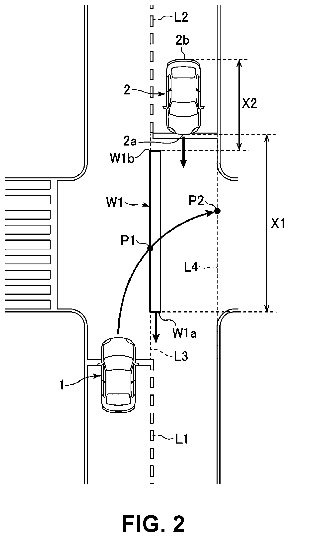
[0047]First, an automatic brake control according to a first embodiment of the present disclosure will be described with reference to FIG. 2. FIG. 2 shows a situation where the own vehicle 1 is attempting to traverse the opposite lane by turning right at an intersection (this is in reference to driving in Japan, where an intersection is crossed when turning right, in a similar manner to how a vehicle traverses an opposite lane when turning left in an intersection in the US).

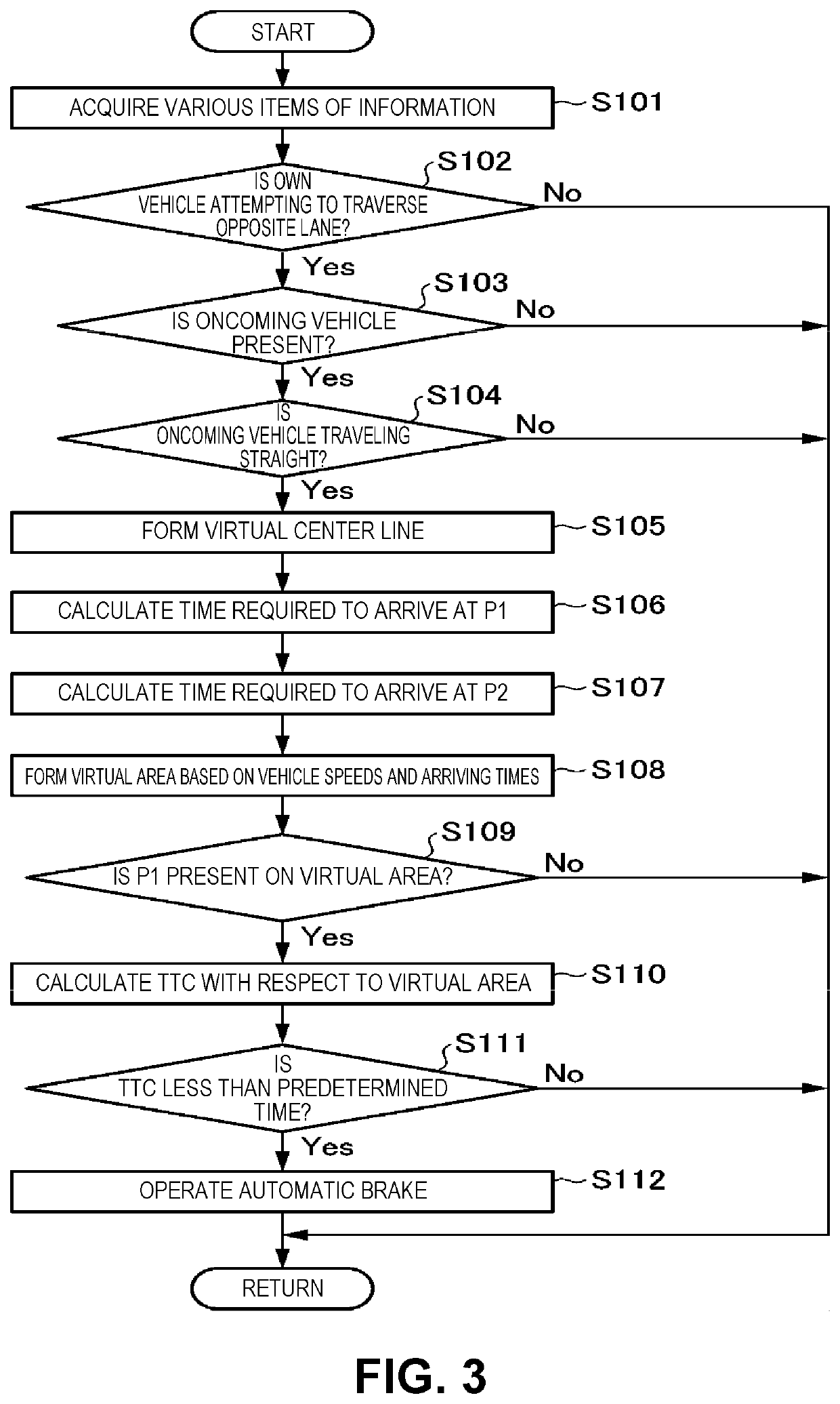
[0048]In the flowchart shown in FIG. 2, there is a possibility of a collision of the own vehicle 1 with an oncoming vehicle 2. Accordingly, the controller 10 controls the operation of the automatic brake to avoid a collision between the own vehicle 1 and the oncoming vehicle 2. Particularly, in this embodiment, the controller 10 sets a virtual area W1 between the own vehicle 1 and the oncoming vehicle 2, and controls the automatic brake such that the own vehicle 1 is prevented from coming into contact with this v...

second embodiment

[0080]Next, an automatic brake control according to a second embodiment of the present disclosure will be described. Hereinafter, a control and the manner of operation and advantageous effects which are different from those of the first embodiment are mainly described, and the description of a control and the manner of operation and advantageous effects substantially equal to those of the first embodiment is omitted when appropriate.

[0081]FIG. 4 is an explanatory view of the automatic brake control according to the second embodiment of the present disclosure. FIG. 4 also shows a situation where the own vehicle 1 is attempting to traverse an opposite lane by turning right at the intersection.

[0082]As shown in FIG. 4, in the second embodiment, the controller 10 sets a virtual area W2 on a virtual center line L3 between the own vehicle 1 and the oncoming vehicle 2, the virtual area W2 extending toward the own vehicle 1 using a rear end 2b of the oncoming vehicle 2 as a base point. That...

third embodiment

[0088]Next, an automatic brake control according to a third embodiment of the present disclosure will be described. Hereinafter, a control and the manner of operation and advantageous effects which are different from those of the first embodiment are mainly described, and the description of a control and the manner of operation and advantageous effects substantially equal to those of the first embodiment is omitted when appropriate.

[0089]FIG. 6 is an explanatory view of the automatic brake control according to the third embodiment of the present disclosure. FIG. 6 also shows a situation where the own vehicle 1 is attempting to traverse the opposite lane by turning right at the intersection.

[0090]In the example shown in FIG. 6, the center line is not drawn on a road and hence, the controller 10 cannot form the virtual center line L3 as in the case of the above-mentioned first embodiment (see FIG. 2). In the third embodiment, when the controller 10 cannot form the virtual center line ...


PUM


Abstract

A vehicle control device includes an oncoming vehicle detection sensor that detects an oncoming vehicle approaching an own vehicle; and a controller configured to automatically apply brakes to the own vehicle to avoid a collision with the oncoming vehicle, detected by the oncoming vehicle detection sensor, under a condition that the own vehicle is at least partially in an opposite lane or a planned path of the own vehicle is at least partially in the opposite lane. The controller is further configured to set, between the own vehicle and the oncoming vehicle, a virtual area that moves with the oncoming vehicle and that extends toward the own vehicle using a rear end of the oncoming vehicle as a base point, and automatically brake the own vehicle to avoid the own vehicle coming into contact with the virtual area to avoid the collision between the own vehicle and the oncoming vehicle.

Description

CROSS-REFERENCE TO RELATED APPLICATION[0001]The present application claims priority to JP 2019-079965, filed Apr. 19, 2019, the entire contents of which are incorporated herein by reference.BACKGROUNDField of the Disclosure[0002]The present disclosure relates to a vehicle control device which assists traveling of a vehicle.Description of the Related Art[0003]Conventionally, to avoid a collision between an own vehicle (i.e., the subject vehicle) and a predetermined object (an oncoming vehicle, a preceding vehicle, a pedestrian, an obstacle or the like) around the own vehicle, a technique relating to an automatic brake for causing the own vehicle to be automatically braked has been proposed. For example, Japanese Patent Laid-Open No. 2018-95097 (patent document 1) discloses a technique where the crossing position of the travel locus of the own vehicle and the travel locus of an oncoming vehicle is acquired, and the automatic brake is controlled corresponding to the time required for t...

Claims


Application Information

Patent Timeline
IPC IPC(8): B60W30/09B60W30/095B60W40/04B60W10/18B60T7/22G08G1/16G06K9/00
CPCB60T7/22G08G1/167B60W30/09B60W30/0956G06K9/00805B60T2201/024B60W10/18B60W2554/804B60T2201/022B60W2754/50B60W2420/42B60W40/04B60W30/0953B60W30/18154B60W30/18159B60W2050/143B60W2554/4041B60W2554/4042G06V20/58B60W2420/403
Inventor OHMURA, HIROSHINAKAGAMI, TAKASHICHEN, XI
Owner MAZDA MOTOR
Why Eureka
Try Eureka