Rotor, motor and rotor manufacturing method

A manufacturing method and rotor technology, applied in the manufacture of motor generators, stator/rotor bodies, magnetic circuit rotating parts, etc., can solve problems such as contact between the belt and the stator, and achieve contact suppression, suppression of noise, and contact between the belt and the stator The effect of the contact

Active Publication Date: 2017-11-03
NIDEC SANKYO CORP
View PDF5 Cites 0 Cited by
  • Summary
  • Abstract
  • Description
  • Claims
  • Application Information

AI Technical Summary

Problems solved by technology

Therefore, there is a problem that the portion of the belt floating from the permanent magnet vibrates, causing noise and contact between the belt and the stator.

Method used


Image

  • Rotor, motor and rotor manufacturing method
  • Rotor, motor and rotor manufacturing method
  • Rotor, motor and rotor manufacturing method

Examples


Embodiment Construction

[0050] Hereinafter, a rotor and a motor using the present invention will be described with reference to the drawings. In the following description, the side where the rotating shaft protrudes in the direction in which the axis of the rotating shaft (motor axis L) extends is the output side L1, and the side (the other side) opposite to the side where the rotating shaft protrudes is The output opposite side L2 will be explained.

[0051] (overall structure of the motor)

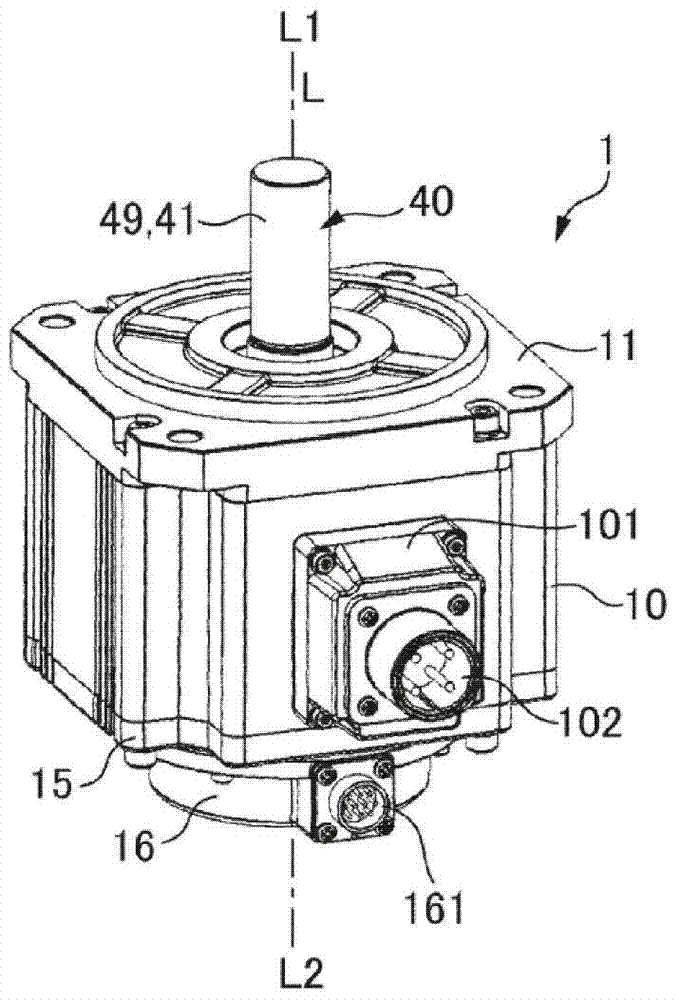
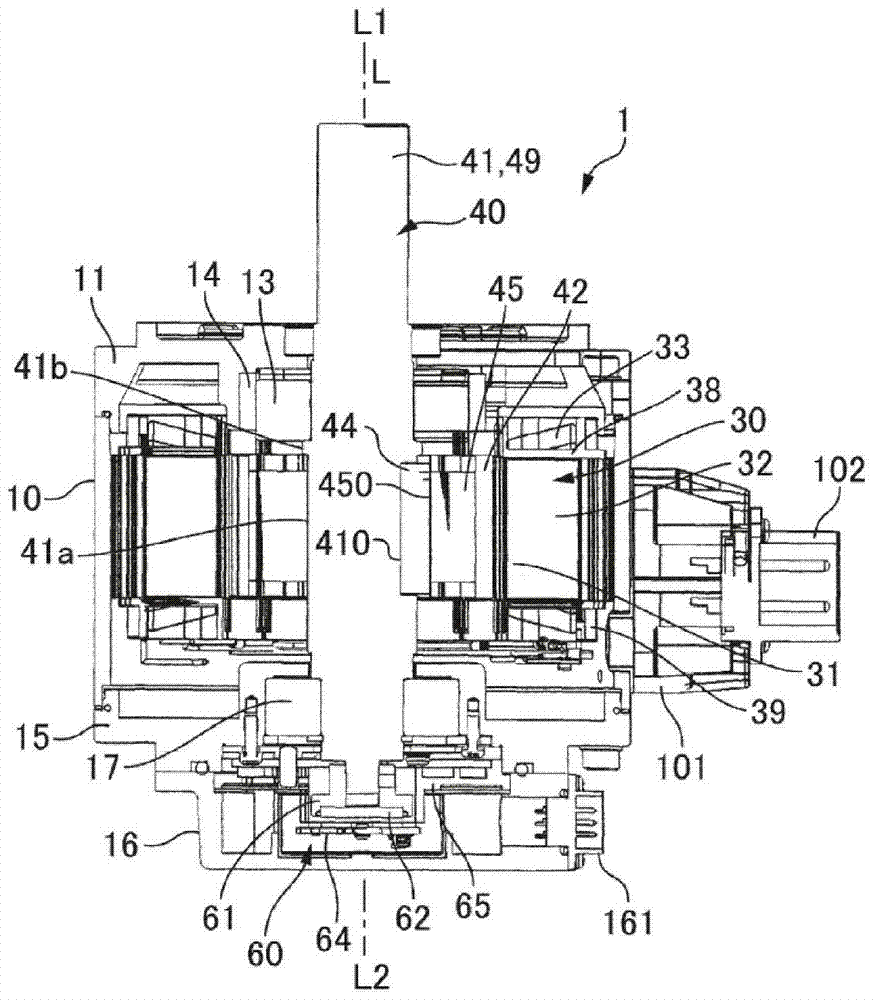
[0052] Fig. 1 (a), Fig. 1 (b) are explanatory diagrams using the motor 1 of the present invention, Fig. 1 (a) is the perspective view of the motor 1 observed from the output side L1, Fig. 1 (b) is the longitudinal direction of the motor 1 Cutaway.

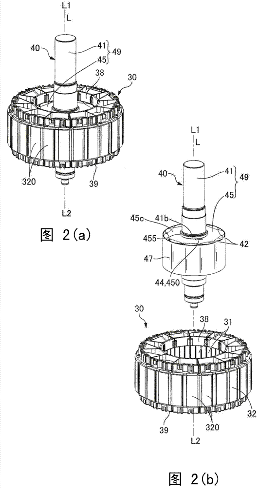
[0053]The motor 1 shown in Fig. 1 (a) and Fig. 1 (b) is a permanent magnet type synchronous motor, and has a square tubular iron core holder 10, a cylindrical stator 30 arranged inside the iron core holder 10, The rotor 40 arranged inside the stator 30 and the en...


PUM


Abstract

Disclosed are a rotor, a motor and a manufacture method of the rotor. The rotor is capable of fixing permanent magnets more reliably on a rotating shaft through a belt which winds the periphery of the plurality of permanent magnets and inhibiting vibration of parts of the belt, floating between the permanent magnets. In the rotor (40), the plurality of permanent magnets (42), outer peripheral surfaces (422) of which are curved surfaces, are fixed on an outer peripheral surface (45f) of a rotator iron core (45) of the rotating shaft (49). The belt (47) winds the radial outer sides of the permanent magnets (42) and the belt (47) is fixed on the outer peripheral surfaces (422) of the plurality of permanent magnets (42) through an adhesive. Between two adjacent permanent magnets (42), a part of the belt (47) enters a position which is at the inner side than an imaginary externally tangent line (P) of the outer peripheral surfaces (422) of the two permanent magnets (42). Therefore, between two permanent magnets (42), the part of the belt (47), floating from the permanent magnets (42), is comparatively short.

Description

technical field [0001] The present invention relates to a rotor in which a plurality of permanent magnets are fixed on the outer peripheral surface of a rotating shaft, a motor, and a method for manufacturing the rotor. Background technique [0002] In rotors used for motors, generators, etc., a plurality of permanent magnets are fixed to the outer peripheral surface of the rotating shaft. Furthermore, in order to achieve the purpose of preventing permanent magnets from flying, a technique has been proposed in which a tape is annularly wound around the rotor so as to surround the permanent magnets, and the tape is adhesively fixed to the outer peripheral surface of the permanent magnets ( Refer to Patent Document 1). [0003] Patent Document 1 Japanese Unexamined Patent Publication No. 2013-9458 [0004] As shown in the structure of Patent Document 1, in order to wind the tape so that the outer peripheral surface of the permanent magnet is in close contact with the tape, t...

Claims


Application Information

Patent Timeline
IPC IPC(8): H02K1/28H02K1/27H02K15/03
CPCH02K1/27H02K1/28H02K15/03
Inventor 松村修太
Owner NIDEC SANKYO CORP
Why Eureka
Try Eureka