Supercharge Your Innovation With Domain-Expert AI Agents!

Indoor device of air conditioner

A technology for indoor units and air conditioners, applied in air conditioning systems, space heating and ventilation, space heating and ventilation details, etc., can solve the problems of poor sealing effect, many assembly processes, and imprecise assembly, and avoid strict Sexual problems or thermal expansion and contraction, improve running quality, reduce the number of parts

Active Publication Date: 2013-05-15
GREE ELECTRIC APPLIANCES INC
View PDF0 Cites 0 Cited by
  • Summary
  • Abstract
  • Description
  • Claims
  • Application Information

AI Technical Summary

Problems solved by technology

[0003] In the indoor unit of the air conditioner, the drainage system is an important part, such as figure 1 As shown, it is a structural schematic diagram of an indoor unit of an air conditioner in the prior art. The indoor unit includes various parts or components such as a front water tank, a rear water tank, a water diversion tank, and a water outlet, and these parts or components are Separate design, so that when performing production process operations, it is necessary to open multiple molds separately to manufacture these separate parts or components, and it takes more work to assemble these separate parts or components. Lead to increased production costs and low production efficiency
In addition, due to the many assembly processes and complex assembly relationships of parts or components, various assembly problems are prone to occur. For example, when the parts or components are not tightly assembled, water leakage problems are likely to occur. The effect is not good, and it is also prone to condensation problems caused by air leakage. In addition, after the indoor unit is installed, due to the large number of parts or components, there are many coordination relationships, and the degrees of thermal expansion and contraction of each part are not the same. , when the air conditioner is running, it is also prone to abnormal noise caused by thermal expansion and contraction

Method used


Image

  • Indoor device of air conditioner
  • Indoor device of air conditioner
  • Indoor device of air conditioner

Examples


Embodiment Construction

[0047] A preferred embodiment of the present invention will be described in detail below.

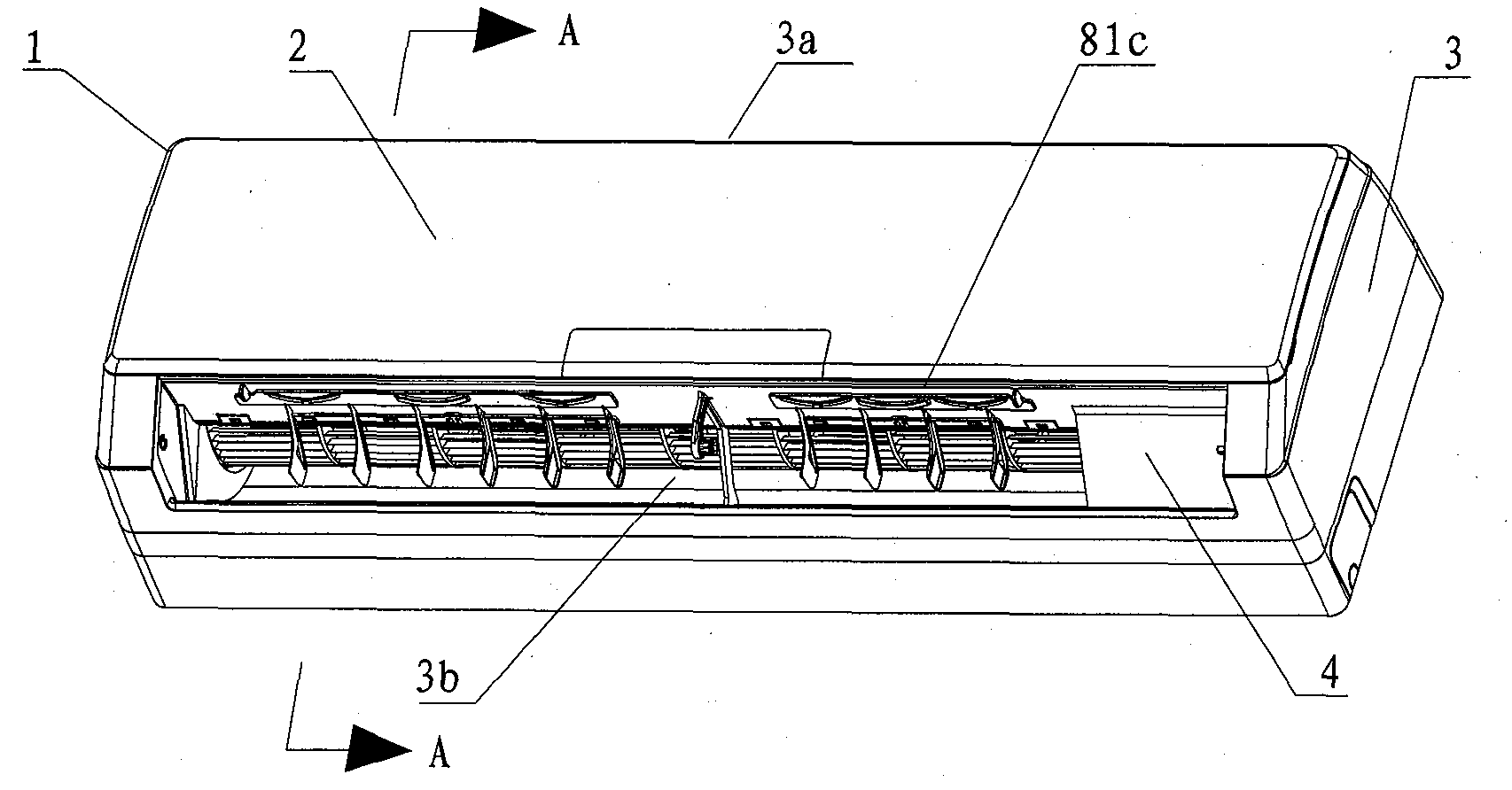
[0048] Such as figure 2 Shown is a schematic view of the appearance of a preferred embodiment of the indoor unit of the present invention. The main body 1 of the indoor unit includes a panel 2, a casing 3 and a bottom casing 4. The panel 2 is arranged on the front surface of the casing 3, and the casing 3 contains the bottom casing 4 inside. The air port 3a is provided with an exhaust port 3b at the lower front portion of the casing 3 .

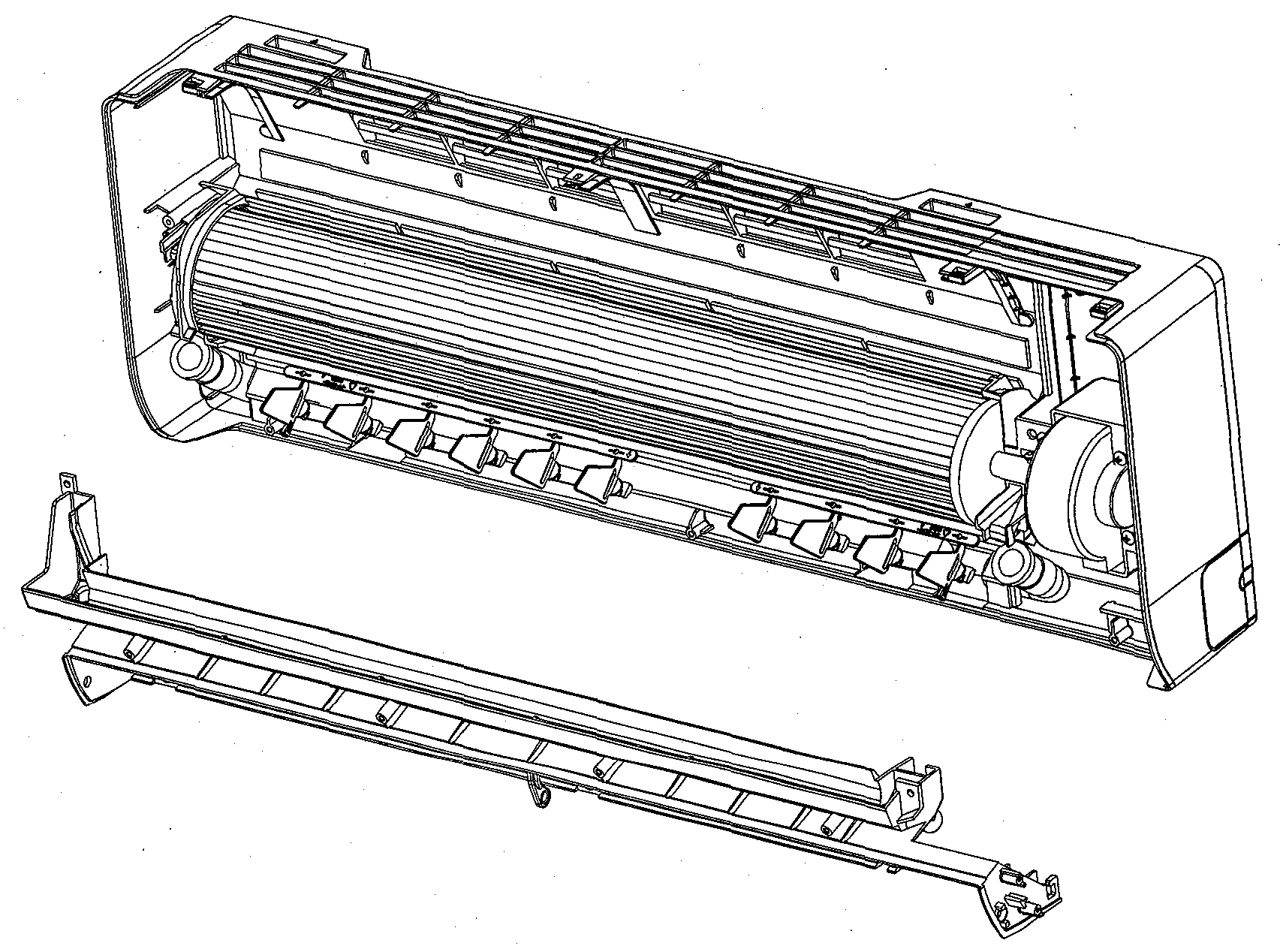
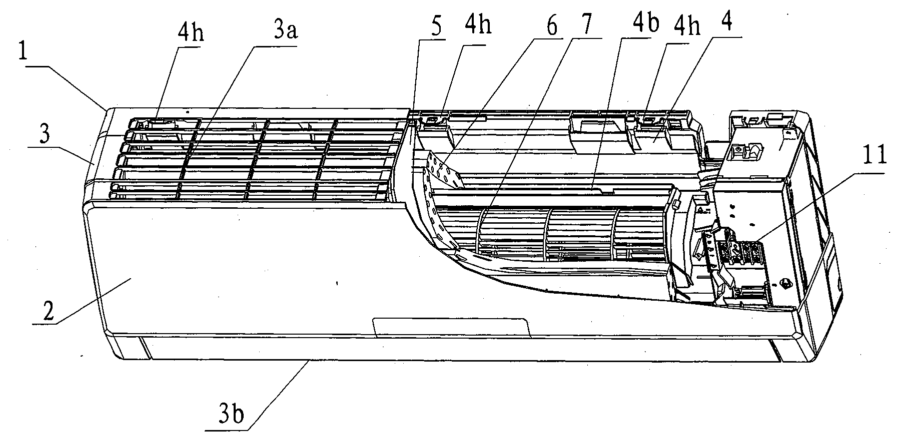
[0049] Such as image 3 As shown, a ventilator 7 is provided inside the indoor unit 1, and an air filter 5 and a heat exchanger 6 are provided half-surrounding the upper end of the ventilator 7 in the direction of the air inlet, and the air filter 5 Outside the heat exchanger 6, to filter the air entering the indoor unit 1 to ensure the quality of the air entering the indoor unit 1, so as to effectively protect the performance and life of the indoo...


PUM


Abstract

The invention relates to an indoor device of an air conditioner, comprising a main body which is composed of a panel, an outer shell and a bottom shell, a ventilator which is arranged in the main body, a heat exchanger which is arranged in the main body and is half-surrounded along the peripheral direction of the ventilator, the heater exchanger comprises a front side heat exchanger and a back side heat exchanger, the heater exchanger further comprises a front water holding channel with a groove, which is arranged below the front side heat exchanger, and a back water holding channel with a groove, which is arranged below the back side heat exchanger, the back water holding channel is obliquely arranged, the lower end of the back water holding channel is connected with the corresponding end of the front water holding channel by a first water drainage channel, water draining holes are arranged at the bottom part of two ends of the front water holding channel; the bottom shell, the frontwater holding channel, the back water holding channel and the first water drainage channel are integrated. The corresponding bottom shell and the related devices thereof are manufactured by a mould when the indoor device of the air conditioner is manufactured, the component account is reduced, and the assembling procedure is reduced, and the production efficiency is greatly increased.

Description

technical field [0001] The invention relates to the field of household appliances, in particular to an indoor unit of an air conditioner in the field of air conditioning. Background technique [0002] In the existing air-conditioning technology field, in order to achieve the effect of aesthetics, an air conditioner combining an indoor unit and an outdoor unit is usually used. machine connected. [0003] In the indoor unit of the air conditioner, the drainage system is an important part, such as figure 1 As shown, it is a structural schematic diagram of an indoor unit of an air conditioner in the prior art. The indoor unit includes various parts or components such as a front water tank, a rear water tank, a water diversion tank, and a water outlet, and these parts or components are Separate design, so that when performing production process operations, it is necessary to open multiple molds separately to manufacture these separate parts or components, and it takes more work...

Claims


Application Information

Patent Timeline
Patent Type & Authority Patents(China)
IPC IPC(8): F24F1/00F24F13/22F24F13/30
Inventor 张辉钟明生黄辉陈绍林骆海杨检群
Owner GREE ELECTRIC APPLIANCES INC
Features
  • R&D
  • Intellectual Property
  • Life Sciences
  • Materials
  • Tech Scout
  • Unparalleled Data Quality
  • Higher Quality Content
  • 60% Fewer Hallucinations
Learn More