Test bench for tightness of oil conduit of engine camshaft

A technology for testing benches and camshafts, which is applied in the direction of liquid tightness measurement using liquid/vacuum degree, and detecting the appearance of fluid at leakage points, etc. It can solve the problems of preventive measures, lack of detection tools and methods, etc., and achieve Easy to operate, ingenious effect

Inactive Publication Date: 2010-06-23
重庆动源摩托车配件销售有限公司
View PDF0 Cites 4 Cited by
  • Summary
  • Abstract
  • Description
  • Claims
  • Application Information

AI Technical Summary

Problems solved by technology

But at present, there is no effective detection tool and method, and no corresponding preventive

Method used


Image

  • Test bench for tightness of oil conduit of engine camshaft
  • Test bench for tightness of oil conduit of engine camshaft
  • Test bench for tightness of oil conduit of engine camshaft

Examples


Embodiment Construction

[0019] Below in conjunction with accompanying drawing and embodiment the present invention will be further described:

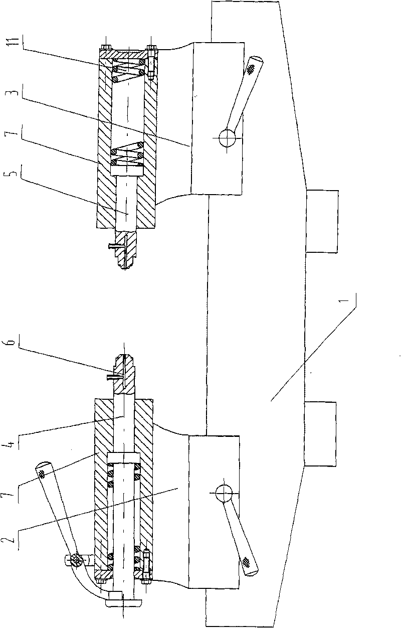
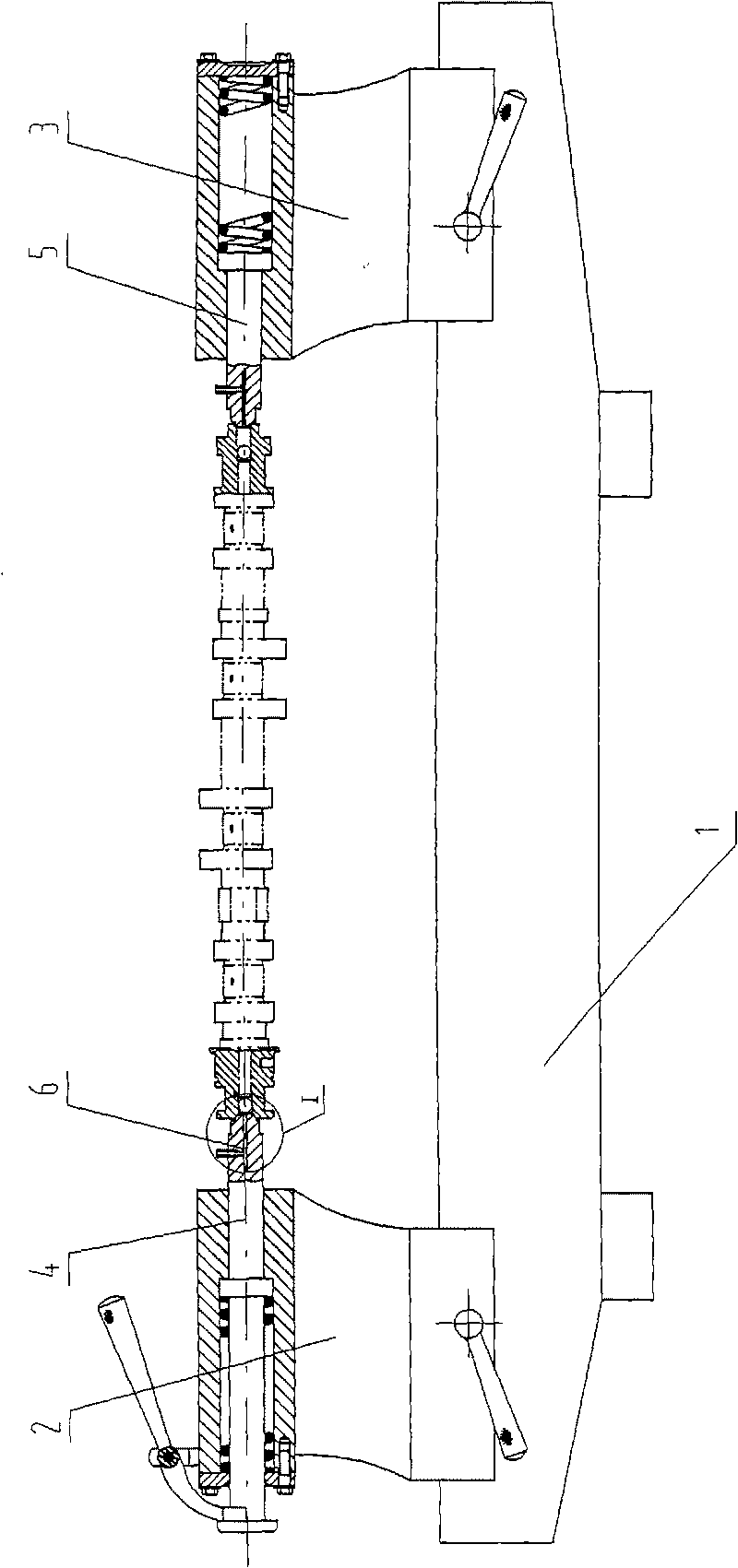
[0020] Examples such as figure 1 , 2 , 4, 5, and 6 show 1. a test bench for engine camshaft oil passage tightness, including a base 1, a front slide 2 and a rear slide 3, wherein the front slide 2 and the rear slide 3 can be Slide horizontally on the base 1, a front push rod 4 is set in the front slide table 2, a rear push rod 5 is set in the rear slide table 3, the shafts of the front push rod 4 and the rear push rod 5 The center line is on the same horizontal straight line, and the front end of at least one of the front ejector rods 4 and rear ejector rods 5 is provided with an air passage 6, and the air inlet of the air passage 6 is arranged on the front end side wall of the ejector rod. The air port is arranged on the end face of the front end of the ejector rod, the shape of the front end of the ejector rod matches the shape of the process hole 13 at ...


PUM


Abstract

The invention discloses a test bench for tightness of an oil conduit of an engine camshaft, which comprises a base, a front sliding way and a rear sliding way. An ejector rod is sleeved in the front sliding way and the rear sliding way respectively. Axial leads of the two ejector rods are positioned in the same horizontal line. A front end of at least one ejector rod is provided with an air passage. An air inlet of the air passage is formed on a side wall of the front end of the ejector rod, and an air outlet is formed on the end face of the front end head of the ejector rod. The shape of the front end head of the ejector rod is a tapered end head matched with the shape of a technology hole at an opening of the oil conduit of the camshaft to be tested. A step surface is formed at the front end of the ejector rod close to the tapered end head. A seal gas ring is sleeved on the step surface, so that an air-tight seal is formed between the technology hole and the front end head of the ejector rod during detection. The test bench has the advantages of ingenious conception and convenient operation, and can effectively test the tightness of the oil conduit of the engine camshaft.

Description

technical field [0001] The invention belongs to the technical field of engine inspection tools, and in particular relates to an engine camshaft oil passage sealing test bench. Background technique [0002] In the engine, the camshaft is installed on the engine cylinder head. In order to ensure the good operation of the engine, oil must be lubricated between the camshaft journal and the camshaft journal hole of the engine cylinder head to reduce friction and prevent the camshaft from locking. At present, the left end of the camshaft is used to set the oil inlet hole 14 (such as image 3 As shown), the engine oil pump pumps oil, and the oil enters the oil hole 14 through the oil passage opened by the cylinder block, the cylinder head, etc., and injects lubricating oil into the camshaft oil passage, and the camshaft oil passage runs through the shaft center of the entire camshaft At the same time, the lubricating oil outlet hole 15 is set on the camshaft, and the lubricating oi...

Claims


Application Information

Patent Timeline
IPC IPC(8): G01M3/08
Inventor 张志发文江强陈媚
Owner 重庆动源摩托车配件销售有限公司
Why Eureka
Try Eureka