Supercharge Your Innovation With Domain-Expert AI Agents!

Lens module

A lens module and coil group technology, applied in installation, optics, instruments, etc., can solve problems such as falling off, magnet 14 cannot be attached tightly, small size, etc., and achieve the effect of simple design

Inactive Publication Date: 2010-06-23
SKINA OPTICAL
View PDF0 Cites 23 Cited by
  • Summary
  • Abstract
  • Description
  • Claims
  • Application Information

AI Technical Summary

Problems solved by technology

[0012] 1. Please refer to Figure 2C , Figure 2B As shown, it can be clearly seen that any magnet has a circular arc surface 141, which is to match the four chamfers 1322 of the annular outer wall structure 132 in the yoke 13, so that the magnet 14 can be smoothly Attached to the inner surface 1321 of the chamfer 1322; however, because the curvature of the chamfer 1322 is not easy to control its processing accuracy in the actual manufacturing process, it is possible to produce the arc surface 141 of the magnet 14 The curvature is not consistent with the curvature of the chamfer 1322, so that the magnet 14 cannot be tightly attached to the chamfer 1322, resulting in falling off
[0013] 2. Because the size of the above-mentioned lens module 10 is generally very small, for the combination structure design between the limit hole 16211 in the fixing cylinder 16 and the limit guide post 193 in the lower joint 19, It is often easy to break the position-limiting guide post 193 during the assembly process, resulting in inaccurate assembly; and, because the position-limiting hole 16211 needs to have a certain aperture depth to exert an assembly effect, such a Therefore, the height of the ring-shaped bearing flange 1621 extending from the bottom 162 of the barrel body cannot be effectively reduced, thereby affecting the effect of reducing the overall size of the lens module.

Method used


Image

  • Lens module
  • Lens module
  • Lens module

Examples


Embodiment Construction

[0119] A preferred embodiment is listed below to illustrate the present invention, but those familiar with the art know that this is only an example, and is not intended to limit the invention itself; function or a lens module with Auto Macro function.

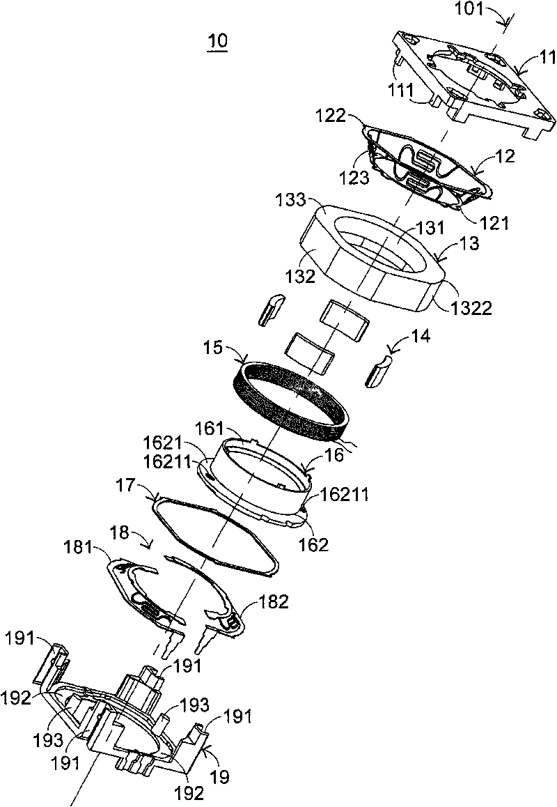
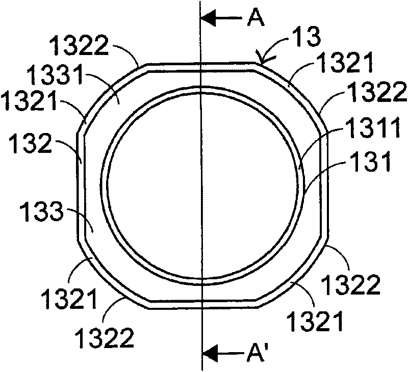
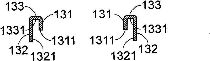
[0120] Please see first Figure 5 , Figure 7A to Figure 7C , Figure 9A , 9B , Figure 10A , 10B ;in, Figure 5 It is an exploded schematic diagram of a better lens module driven and controlled by a voice coil motor in this case; Figure 7A to Figure 7C Shown are the top view schematic diagram and the bottom view schematic diagram of the yoke in the aforementioned preferred embodiment, and the side view schematic diagram along the DD' sectional line; Figure 9A as well as Figure 9B Shown are respectively the bottom view schematic diagram and the side view schematic diagram along the FF' section line of the fixed cylinder in the aforementioned preferred embodiment; Figure 10A as well as Figure 10B Shown are a sche...


PUM


Abstract

The invention discloses a lens module, which at least comprises an upper connector, a spring piece, a magnet yoke, a plurality of magnets, a coil assembly, a fixed cylinder and a lower connector which includes a lower shell and a base, wherein the magnet yoke is arranged below the spring piece and is provided with a hollow cylindrical inner wall, a plurality of plate structures which are arranged along the radial direction of the hollow cylindrical inner wall and are axially extended downwards, a wall top connected with the hollow cylindrical inner wall, and top part surfaces of the plate tops of the plate structures; therein, the plate structures which are arranged at interval at the periphery of the top part surfaces are arranged at the outer side of the hollow cylindrical inner wall; in addition, the bottom part of the fixed cylinder body is distributed circumferentially and is provided with at least two bulge structures at interval, and the bottom part of the lower connector is provided with at least two sunk parts which are matched with the two bulge structures.

Description

technical field [0001] The present invention relates to a lens module, in particular to a lens module driven and controlled by a voice coil motor (Voice Variable Motor, VCM). Background technique [0002] At present, in the field of lens module technology, since the driving control method of voice coil motor (Voice Variable Motor, VCM) has the advantages of relatively reducing the size of the overall lens module and low cost, it has been widely used. It can be applied to lens modules with Auto Focus and Auto Macro functions. [0003] see Figures 1 to 4B ;in, figure 1 It is an exploded schematic view of a known lens module driven and controlled by a voice coil motor; Figure 2A as well as Figure 2B Shown are respectively the bottom view schematic diagram and the side view schematic diagram along the AA' sectional line of the yoke in the aforementioned known lens module; Figure 2C Shown is an enlarged schematic diagram of several magnets in the aforementioned known len...

Claims


Application Information

Patent Timeline
Patent Type & Authority Applications(China)
IPC IPC(8): G02B7/02G02B7/09H02K33/18
Inventor 陈亮任吴振弘
Owner SKINA OPTICAL
Features
  • R&D
  • Intellectual Property
  • Life Sciences
  • Materials
  • Tech Scout
  • Unparalleled Data Quality
  • Higher Quality Content
  • 60% Fewer Hallucinations
Learn More