Antenna positioning device

A positioning device and antenna technology, which is applied to antenna supports/installation devices, antennas, electrical components, etc., can solve the problems of poor antenna positioning reliability, easy swing of antenna rods, poor stability of received signals, etc., and achieves reliable use and structure. Compact, easy-to-install effect

Inactive Publication Date: 2010-06-23
力帆科技(集团)股份有限公司
View PDF1 Cites 11 Cited by
  • Summary
  • Abstract
  • Description
  • Claims
  • Application Information

AI Technical Summary

Problems solved by technology

Although the above structure can realize the rotation and anti-theft of the antenna, the reliability of the antenna positioning is poor, the antenna pole is easy to swing, and the stability of the received signal is poor

Method used


Image

  • Antenna positioning device
  • Antenna positioning device
  • Antenna positioning device

Examples


Embodiment Construction

[0024] Below in conjunction with accompanying drawing and embodiment the present invention will be further described:

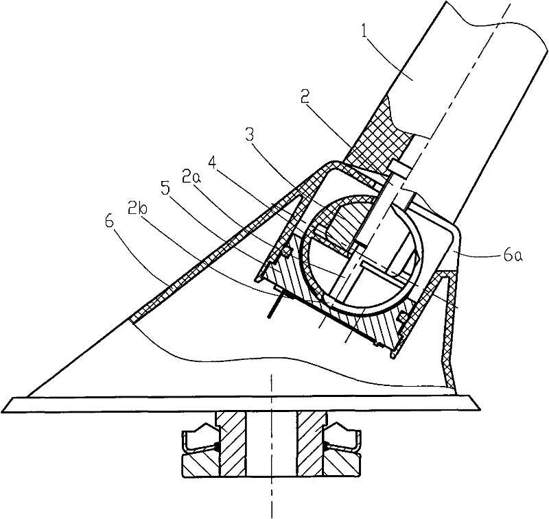
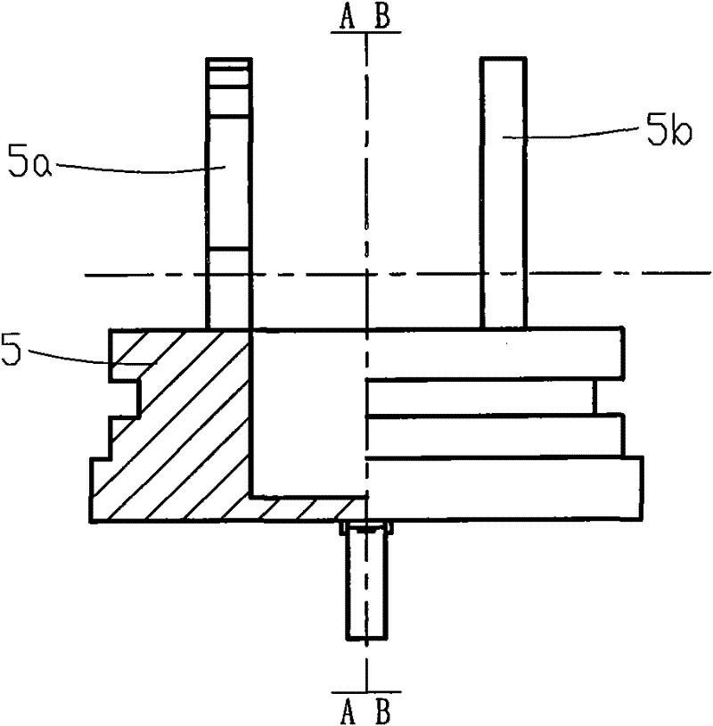
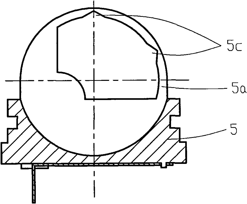
[0025] Such as Figure 1 to Figure 11 As shown, the present invention is made of parts such as antenna rod 1, screw rod 2, rotating connector 3, rotating fixture 4, base 5, outer cover 6 and nut 7. The rear portion at the top of the cover 6 is provided with an installation via hole 6a, and the mounting base 5 is fixed in the cover 6. Two connecting pieces 5a, 5b are fixed side by side on the base 5, and there are holes for rotation on the connecting pieces 5a, 5b. The assembly hole that connector 3 is installed, wherein the assembly hole on the first connecting piece 5a is sector-shaped, and the central angle of this sector is 90 °, and at least two positioning grooves 5c are provided on the inner wall of sector-shaped long arc edge; The assembly hole on the connecting piece 5b is semicircular, and at least two positioning grooves 5c are formed on the inner ...


PUM


Abstract

The invention relates to an antenna positioning device. A screw rod is fixed at the lower end of an antenna rod, the screw rod is matched with a rotating connecting element through screw threads, a first connecting sheet and a second connecting sheet are fixed in parallel on a base, a rotating fixed element is arranged between the two connecting sheets, the rotating fixed element is in an annular structure, a screw nut is embedded on the top of the rotating fixed element, the screw nut and the screw rod are connected through screw threads, the middle of the rotating connecting element is positioned in the rotating fixed element, both ends of the rotating connecting element are provided with assembling steps, each assembling step extends into assembling holes formed on the corresponding connecting sheets, positioning lug bosses are arranged on the assembling steps of the rotating connecting element, and the positioning lug bosses are clamped into positioning grooves formed on the connecting sheets. The inclination angle of the antenna rod can be regulated as required, the regulation is convenient, the operation is simple, and in addition, the antenna rod has reliable positioning at a certain inclination angle without swinging. The invention simplifies the structure, simultaneously and effectively reduces the cost, and has the advantages of compact structure, easy installation, antitheft and disconnection prevention effects and reliable use.

Description

technical field [0001] The invention relates to an automobile component, in particular to a positioning device for an automobile rotating antenna. Background technique [0002] A car antenna refers to a mobile communication antenna designed to be installed on a vehicle to receive and enhance radio signals. At present, the antenna pole of the car antenna is generally installed on the roof of the vehicle through the base. Since the antenna pole is fixedly connected to the base, the antenna cannot achieve the best effect of simultaneously receiving broadcasting and wireless telephones at different inclination angles. Chinese patent 200620076806.X disclosed a car antenna rotation anti-theft device on October 17, 2007. A base is installed in the outer cover, an anti-theft gasket is arranged in the base, and two connecting rings are arranged on the base. A rotating connector is installed inside; the lower part of the antenna rod is equipped with a connecting screw, which extends ...

Claims


Application Information

Patent Timeline
Patent Type & Authority Applications(China)
IPC IPC(8): H01Q1/12H01Q3/02
Inventor 陈雨康周映东
Owner 力帆科技(集团)股份有限公司
Why Eureka
Try Eureka