Supercharge Your Innovation With Domain-Expert AI Agents!

Parallel operation control circuit of electric generator

A technology for controlling circuits and generators, applied in the direction of controlling generators, control systems, electrical components, etc., can solve the problems of unstable output, low reliability, complex circuits, etc., to increase reliability, reduce costs, and simplify circuits. Effect

Inactive Publication Date: 2010-06-23
杨慧君
View PDF0 Cites 0 Cited by
  • Summary
  • Abstract
  • Description
  • Claims
  • Application Information

AI Technical Summary

Problems solved by technology

like figure 1 As shown, in a DC generator, multiple generators are paralleled by controlling the current (magnetic field strength) of the "excitation winding" to balance the output voltage of two or more generators, so that the voltages of each generator are equal. The control circuit is Use one of the generator voltages as a reference, or as a mutual reference (this requires a more complex control circuit); such as figure 2 As shown, in the alternator, the parallel machine of multiple generators must set the frequency, phase, output control and other circuits at its output end, and the circuit is more complicated
[0003] Therefore, whether it is DC or AC generator paralleling, there are many auxiliary equipment, complex circuits, high cost, low reliability, and unstable output.

Method used


Image

  • Parallel operation control circuit of electric generator
  • Parallel operation control circuit of electric generator
  • Parallel operation control circuit of electric generator

Examples


Embodiment Construction

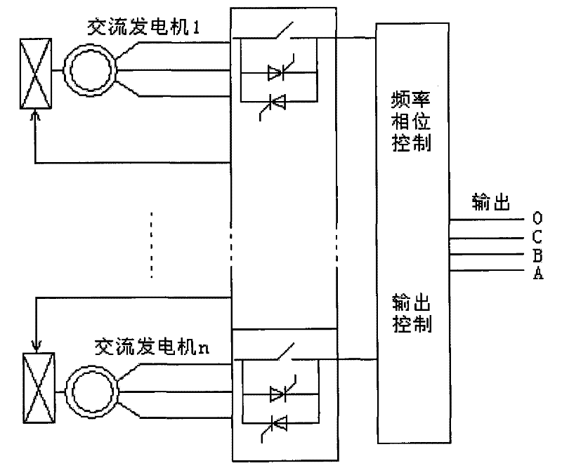
[0015] Refer below image 3 An embodiment of the generator parallel control circuit provided by the present invention is described in detail. This embodiment mainly includes a node weighting circuit 1 formed by connecting two or more generator directional circuits in parallel. The output end of the parallel generator directional circuit is connected to the node Q of the node weighting circuit to form a node The current input terminal of Q, while its current output terminal is connected to the total load R and forms a loop with the node weighting circuit 1 .

[0016] During specific implementation, the generator orientation circuit includes a voltage dividing unit r1 (r2, ...rn) and an orientation unit 10 which are sequentially connected in series with the positive pole of the generator E1 (E2, ... En).

[0017] During specific implementation, the voltage dividing device is a resistor r1, r2, ... rn whose resistance value is smaller than the total load R; the generators E1, E2...


PUM


Abstract

The invention discloses a parallel operation control circuit of an electric generator, which comprises a node weighting circuit which is formed by the mutual parallel connection of at least two of electric generator positioning circuits; the output ends of the electric generator positioning circuits which are connected with each other in parallel are connected with one node of the node weighting circuit to form into the input end of the electric current of the node; and the output end of the electric current is connected with total load to form into a loop with the node weighting circuit. The control circuit is simple, has high reliability, can greatly reduce the cost, has stable output, and is not influenced by environments and fields.

Description

technical field [0001] The invention relates to the field of generators, in particular to a generator parallel control circuit. Background technique [0002] When the generator supplies power to the load, the power of the load may be much greater than the power of a single generator, resulting in insufficient power of the generator to drive the load. In this case, the usual solution is to combine multiple generators to supply power to the load, which is called "parallel generator". In the prior art, the conditions for the parallel operation of generators are relatively strict. For the parallel operation of DC generators, the output voltage of each generator must be the same; for the parallel operation of AC generators, the output voltage and frequency of each generator must be equal. , same phase. figure 1 with figure 2 A control circuit block diagram of parallel DC generators and parallel AC generators is shown respectively. Such as figure 1 As shown, in a DC generato...

Claims


Application Information

Patent Timeline
Patent Type & Authority Applications(China)
IPC IPC(8): H02P9/00
Inventor 杨慧君
Owner 杨慧君
Features
  • R&D
  • Intellectual Property
  • Life Sciences
  • Materials
  • Tech Scout
  • Unparalleled Data Quality
  • Higher Quality Content
  • 60% Fewer Hallucinations
Learn More