Probe swinging mechanism for performing ultrasonic detection on omega welding line of control bar driving mechanism

A driving mechanism, ultrasonic inspection technology, applied in the direction of material analysis, measurement device, instrument, etc. using sonic/ultrasonic/infrasonic waves, can solve the problems of inability to implement, inability to achieve continuous full inspection, and discontinuity of inspection positions, to ensure The effect of safe operation

Active Publication Date: 2010-06-30
CHINA NUCLEAR POWER OPERATION TECH
View PDF0 Cites 26 Cited by
  • Summary
  • Abstract
  • Description
  • Claims
  • Application Information

AI Technical Summary

Problems solved by technology

Routine ultrasonography cannot be performed
[0003] Due to the limitation of the position of the Ω weld I, at present, it is generally used to arrange multiple probes in the circumferential direction of the control rod drive mechanism to realize the full inspection of the cross section by arranging multiple probes in the circumferential direction of the upper Ω weld I. The inspection position of the probes in the circumferential direction of the Ω weld I is still discontinuous, and it is impossible to realize continuous full inspection in the true sense.

Method used


Image

  • Probe swinging mechanism for performing ultrasonic detection on omega welding line of control bar driving mechanism
  • Probe swinging mechanism for performing ultrasonic detection on omega welding line of control bar driving mechanism
  • Probe swinging mechanism for performing ultrasonic detection on omega welding line of control bar driving mechanism

Examples


Embodiment Construction

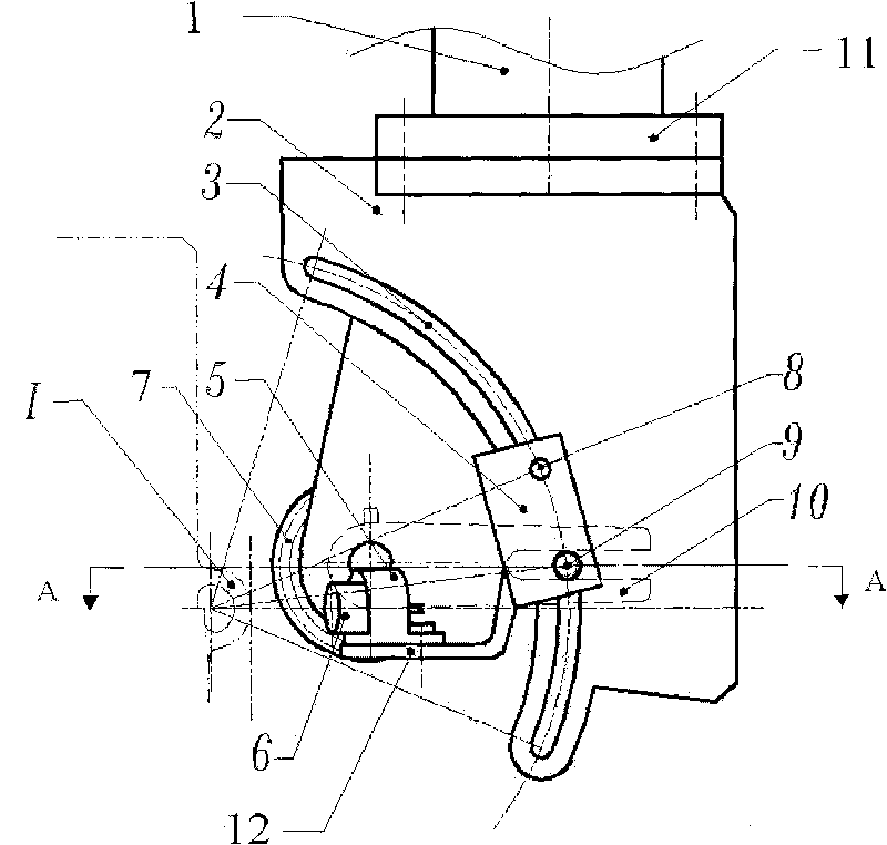
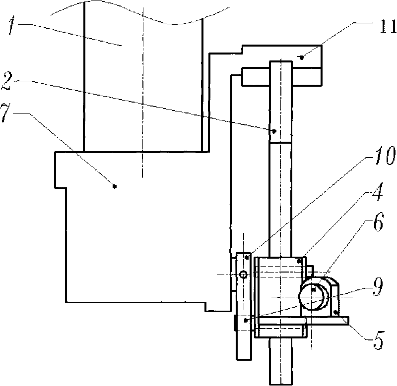
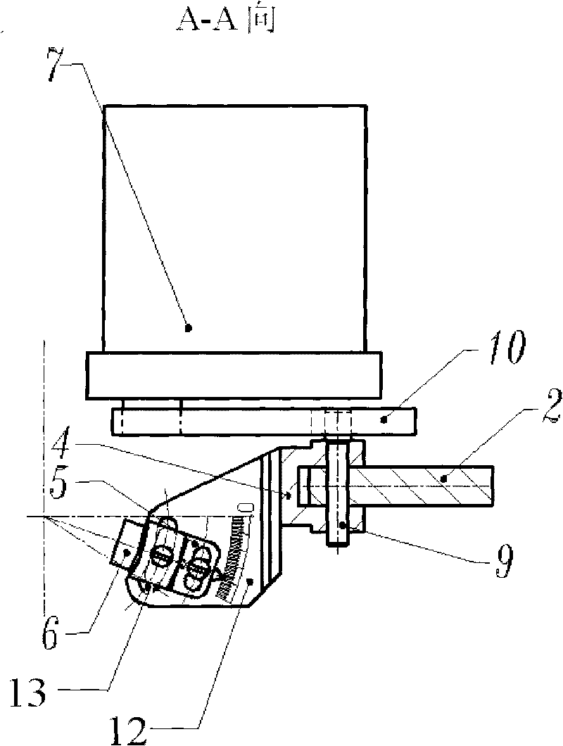
[0013] The probe oscillating mechanism for the ultrasonic inspection of the control rod driving mechanism Ω weld seam provided by the present invention will be further described in detail below with reference to the accompanying drawings and embodiments.

[0014] Such as figure 1 , figure 2 and image 3 , a probe oscillating mechanism for ultrasonic inspection of the control rod drive mechanism Ω weld, it includes a servo motor 1, a gear transmission mechanism 7 connected to the output shaft of the servo motor 1, wherein it also includes a gear transmission mechanism installed on the gear transmission mechanism 7 On the guide rail plate 2 and the probe swing block 4 installed on the guide rail plate 2, there is an arc-shaped guide rail chute 3 concentric with the Ω welding seam I on the guide rail plate 2, and the probe swing block 4 passes through the slide pin 8 and dial The rod 9 is installed on the arc guide rail chute 3, and an arc groove 13 concentric with the Ω weldi...


PUM


Abstract

The invention belongs to a swinging mechanism, which and particularly discloses a probe swinging mechanism for performing ultrasonic detection on an omega welding line of a control bar driving mechanism. The mechanism comprises a servo motor, a gear driving mechanism, a guide rail plate and a probe swinging block, wherein the gear driving mechanism is connected with an the output shaft of the servo motor; the guide rail plate is arranged on the gear driving mechanism; the probe swinging block is arranged on the guide rail plate; the guide rail plate is provided with an arc-shaped guide rail slide groove; and the probe swinging block is arranged on the arc-shaped guide rail slide groove through a sliding pin and a shift rod, and is provided with an arc-shaped groove. A probe clamping device for clamping an ultrasonic probe is arranged in the arc-shaped groove. An The output shaft of the driving mechanism is fixed on and fixedly connected with a shift fork. The front end of the shift fork is used for clamping the shift rod, the shift rod and the probe swinging block are driven by the shifting of the shift fork, and slide along the arc-shaped guide rail slide groove, and then the ultrasonic probe is driven to rotate around the omega weld. The invention can perform continuous ultrasonic overall check around the omega weld.

Description

technical field [0001] The invention belongs to an oscillating mechanism, in particular to a probe oscillating mechanism used for ultrasonic inspection of a control rod driving mechanism Ω welding seam. Background technique [0002] The structure of the upper part of the control rod drive mechanism Ω sealing weld I (abbreviated as Ω weld) is a stainless steel thin-walled tube with an outer diameter of φ11.4mm and a wall thickness of 2.3mm. The materials are 0Cr18Ni9Ti and 1Cr18Ni9Ti. Due to the special structure of the weld, the diameter of the outer circle is small, the wall thickness is very thin, the shape is circular, and there is a driving mechanism in the middle of the weld, which makes the inspection space narrow. Routine ultrasonography cannot be performed. [0003] Due to the limitation of the position of the Ω weld I, at present, it is generally used to arrange multiple probes in the circumferential direction of the control rod drive mechanism to realize the full ...

Claims


Application Information

Patent Timeline
Patent Type & Authority Applications(China)
IPC IPC(8): G01N29/265
Inventor 聂勇蔡家藩丁冬平
Owner CHINA NUCLEAR POWER OPERATION TECH
Why Eureka
Try Eureka