Molten steel sample transporting cylinder

A technology of sample tube and molten steel, applied in conveyors, sampling devices, instruments, etc., can solve the problems of easy overflow of molten steel, easy side rotation, overflow of molten steel, etc.

Inactive Publication Date: 2010-06-30
NANTONG BEICHENG SCI & TECH ENTREPRENEURIAL MANAGEMENT
View PDF0 Cites 2 Cited by
  • Summary
  • Abstract
  • Description
  • Claims
  • Application Information

AI Technical Summary

Problems solved by technology

[0002] When smelting molten steel, by analyzing the composition and content of molten steel, and then controlling the amount of raw materials or other parameters during smelting, the quality of molten steel is guaranteed. Therefore, the testing of molten steel during smelting is a very important step; and the existing large-scale When sampling molten steel in a steel plant, a sampling cylinder is used to transfer the molten steel to the laboratory through a pneumatic sample delivery device. However, the existing sampling cylinders are all equipped with openings on the end faces and sealed with plugs. Due to the temperature of molten steel High, the plug can’t seal the opening of the end face well, and it is easy to make the molten steel overflow; at the same time, just put the sampling cylinder in the air duct pipe, and the sampling cylinder is easy to rotate sideways in the air duct pipe, making the molten steel inside overflow more easily

Method used


Image

  • Molten steel sample transporting cylinder
  • Molten steel sample transporting cylinder

Examples


Embodiment Construction

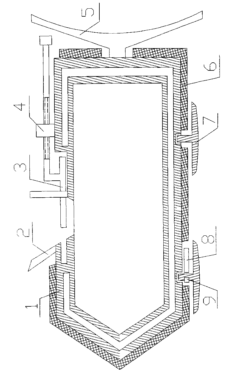
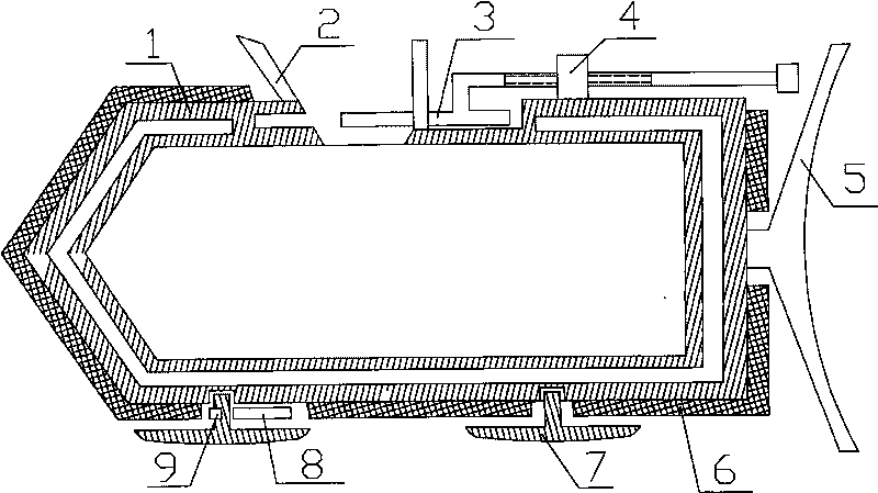
[0013] The accompanying drawing is an embodiment of the present invention, and this embodiment will be described in detail in conjunction with the accompanying drawings, including a sample cylinder 1, a funnel 2, a blocking plate 3, a support 4, a pushing wing 5, an insulating body 6, a sliding plate 7, and a positioning plate 8 and direction block 9; the sample cylinder 1 is set to a cylindrical shape and a cavity filled with molten steel is arranged therein, the top of the sample cylinder 1 is set to be conical and a vacuum chamber is arranged in its wall, and the heat preservation body 6 is arranged in the sample cylinder 1 and is arranged to be fixedly connected with the sample cylinder 1, the upper side of the sample cylinder 1 is provided with an opening and a funnel 2 is arranged at the opening, and the funnel 2 is arranged to be fixedly connected with the sample cylinder 1, and the opening of the sample cylinder 1 A blocking plate 3 is provided, an opening groove is arr...


PUM


Abstract

The invention relates to a molten steel sample transporting cylinder comprising a sample cylinder (1), a blocking plate (3), a support (4), sliding plates (7), a positioning plate (8) and a direction block (9). The upper side surface of the sample cylinder (1) is provided with an opening; the blocking plate (3) is in sealed contact with the sample cylinder (1); the support (4) is fixedly connected with the sample cylinder (1); the blocking plate (3) is in threaded connection with the support (4) by screws; two ends of the lower side surface of the sample cylinder (1) are provided with the sliding plates (7), and the sliding plates (7) is rotationally connected with the sample cylinder (1); the front side surface of the rotating shaft of the sliding plate (7) on the front end is provided with the direction block (9), and the direction block (9) is fixedly connected with rotating shaft; the lower side surface of the sample cylinder (1) at the rear of the rotating shaft of the sliding plate (7) on the front end is provided with the positioning plate (8), and the positioning plate (8) is fixedly connected with the sample cylinder (1); the cross section of the direction block (9) is in the shape of a semicircle; the part where the positioning plate (8) contacts the direction block (9) is provided with a semicircular concave part which corresponds to the direction block (9); and a gap is left between the positioning plate (8) and the direction block (9). Therefore, the molten steel is not easy to overflow.

Description

1. Technical field [0001] The invention relates to a molten steel sample delivery cylinder, in particular to a molten steel sample delivery cylinder suitable for large steel mills. 2. Background technology [0002] When smelting molten steel, by analyzing the composition and content of molten steel, and then controlling the amount of raw materials or other parameters during smelting, the quality of molten steel is guaranteed. Therefore, the testing of molten steel during smelting is a very important step; and the existing large-scale When sampling molten steel in a steel factory, a sampling cylinder is used, and then the molten steel is sent to the laboratory through a pneumatic sample delivery device. However, the existing sampling cylinders are all equipped with openings on the end surface and are sealed with plugs. Due to the temperature of the molten steel, High, the plug can't seal the end face opening well, and the molten steel is easy to overflow; at the same time, ju...

Claims


Application Information

Patent Timeline
IPC IPC(8): G01N35/00G01N1/10B65G51/02
Inventor 崔志远
Owner NANTONG BEICHENG SCI & TECH ENTREPRENEURIAL MANAGEMENT
Why Eureka
Try Eureka