Inspection robot for underground coal mine

A technology for inspection robots and coal mines, applied in the field of inspection robots, can solve the problems of reducing the safety of inspection robots, low wheel grip, slippage, etc., and achieve the effects of easy disassembly, improved grip performance, and easy cleaning.

Inactive Publication Date: 2019-06-11
安徽玄离智能科技股份有限公司
7 Cites 20 Cited by

AI-Extracted Technical Summary

Problems solved by technology

[0003] An existing inspection robot used in coal mines has certain disadvantages in use. First, the existing inspection robot can realize autonomous navigation but cannot flexibly realize autonomous switching when the machine fails, and perform manual operation. If the robot's w...

Method used

By arranging ultrasonic module 20 and multifunctional sensor 13, two ultrasonic probes utilize the principle of ultrasonic positioning to carry out ultrasonic positioning to the front of robot and the area where robot advances on the ground, and play autonomous obstacle avoidance and ditch detection slowing down respectively Ultrasonic detection of potholes and ditches, under the control of the single-chip microcomputer, the four-wheel drive module of the robot reduces the output power to ensure that the robot moves forward slowly and avoids rollover. Realize methane detection, temperature detection, carbon monoxide detection, carbon dioxide detection, hydrogen sulfide detection, sulfur dioxide detection, oxygen detection and wind speed detection, form an integrated detection circuit for real-time monitoring, and transmit the obtained data wirelessly to the remote monitoring terminal through the communication module, So as to realize real-time monitoring.
By the navigation module of setting, by the construction of lidar 14, downhole environment is scanned, thereby obtain three-dimensional imaging, then carry out independent construction map and independent planning route walking by LNM module board 15, thereby realize trackless autonomous navigation, And through the visible light camera 8 and the infrared thermal imager 10 to collect images in real time, if the lens of the visible light camera 8 produces fog, the wiper 7 will slide independently to ensure clear image collection. If the navigation module breaks down, it can be passed on the remote monitoring platform. The WIFI control module is switched to manual operation, which provides an additional layer of guarantee for the use of the entire robot.
It should be noted that the present invention is a kind of inspection robot applied to coal mine underground, first, the robot scans the underground environment through the c...

Abstract

The invention discloses an inspection robot for an underground coal mine. The inspection robot comprises a lower car body and an upper car body, wherein a four-wheel driving module is matched and arranged on the left and right sides of the lower car body, the four-wheel driving module comprises four wheels, a driving motor and a built-in power supply, and both the driving motor and the built-in power supply are installed in the lower car body. According to the inspection robot, a navigation module is arranged, and a laser radar is constructed, so that an underground environment is scanned, anda three-dimensional image is obtained; then a map is independently constructed by virtue of an LNM module board, and a walking route is independently planned, so that railless autonomous navigation is realized; images are collected in real time by a visible light camera and an infrared thermal imager, and if fog is generated on a lens of the visible light camera, a windscreen wiper independentlyslides, so that the clear images are collected; and if the navigation module fails, manual operation can be switched at a remote monitoring station by virtue of a WIFI control module, and a guaranteeis provided for the use of the whole robot.

Application Domain

Technology Topic

Image

  • Inspection robot for underground coal mine
  • Inspection robot for underground coal mine
  • Inspection robot for underground coal mine

Examples

  • Experimental program(3)

Example Embodiment

[0028] Example 1
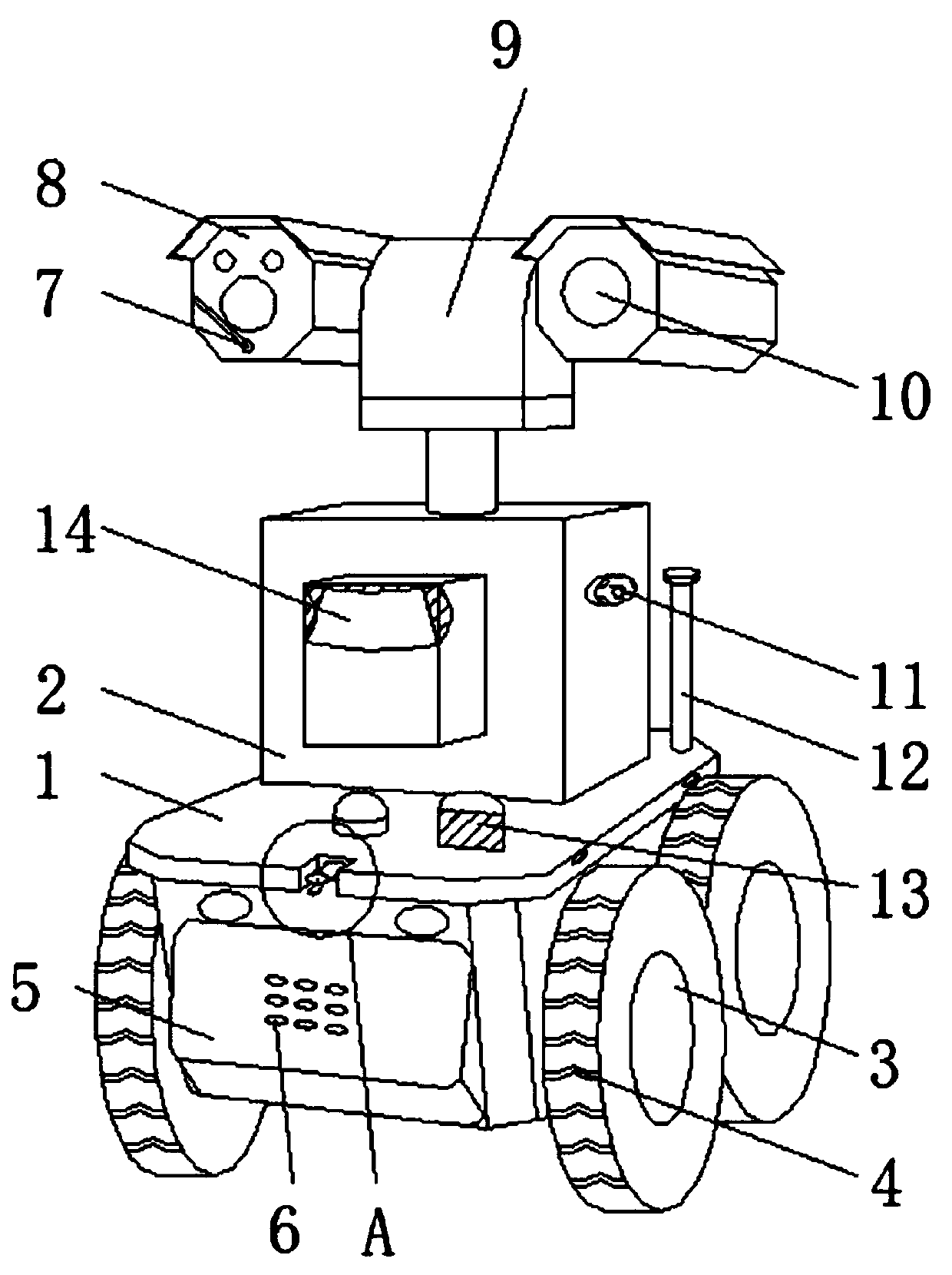
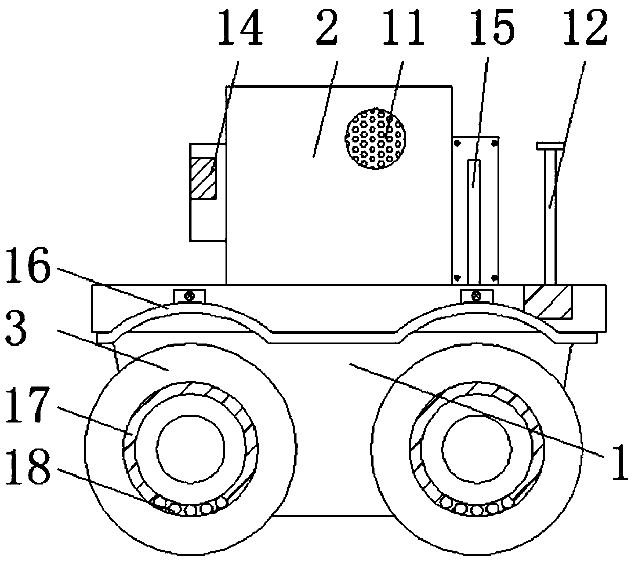
[0029] Such as Figure 1-6 As shown, a patrol robot used in underground coal mines includes a lower body 1 and an upper body 2. Four-wheel drive modules are provided on the left and right sides of the lower body 1, and the four-wheel drive module includes four wheels 3, The motor and the built-in power supply, the drive motor and the built-in power supply are installed in the lower body 1, the front side of the lower body 1 is installed with an anti-collision mechanism 5, and the top of the lower body 1 is installed on the side of the upper body 2 with a multifunctional sensor 13. A communication module is installed on the other side. The communication module includes an antenna 12. A circuit main board 19 is installed inside the lower body 1 and the multi-function sensor 13 and the communication module are electrically connected to the circuit main board 19.
[0030] A navigation module and a pickup 11 are respectively installed around the surface of the upper body 2, and the navigation module includes a lidar 14 and an LNM module board 15, which are respectively located on the front and rear sides of the upper body 2, and the top of the upper body 2 is provided with a camera module , And the camera module includes a visible light camera 8, a pan/tilt 9 and an infrared thermal imager 10. The visible light camera 8 and the infrared thermal imager 10 are respectively installed on both ends of the rotatable part of the pan/tilt 9, and the camera module is electrically connected to the circuit board 19 .
[0031] Such as image 3 As shown, the surface of the circuit main board 19 is spot-welded with a single-chip computer and a WIFI control module, and the type of the single-chip is AT89C51 single-chip, and the single-chip uses PLC programmable technology.
[0032] Such as figure 1 As shown, a wiper 7 is installed at the bottom of the lens of the visible light camera 8, and the wiper 7 is electrically connected to the circuit board 19.
[0033] Through the set navigation module, through the construction of the lidar 14 to scan the downhole environment to obtain three-dimensional imaging, and then use the LNM module board 15 to autonomously construct a map and autonomously plan route walking, so as to achieve track-free autonomous navigation, and through visible light The camera 8 and the infrared thermal imager 10 collect images in real time. If the visible light camera 8 produces fog, the wiper 7 slides autonomously to ensure clear image collection. If the navigation module fails, the module can be controlled via WIFI on the remote monitoring station Switching to manual operation provides an extra layer of protection for the use of the entire robot.

Example Embodiment

[0034] Example 2
[0035] Such as Figure 1-6 As shown, a patrol robot used in underground coal mines. On the basis of embodiment 1, baffles 16 are installed on both sides of the lower body 1 through bolts, and the part of the baffle 16 directly above the wheel 3 is arc-shaped Structure of plastic sheet.
[0036] Such as figure 1 As shown, the wheel surface of the wheel 3 is uniformly provided with arrow-shaped anti-skid patterns 4, and the radial surface of the wheel 3 is evenly provided with an annular groove 17 at the position surrounding the axle, and a number of rolling balls are embedded in the annular groove 17 18.
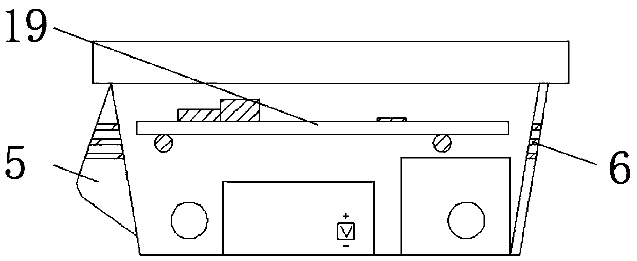
[0037] Such as image 3 As shown, the anti-collision mechanism 5 is made of rubber with a triangular cross-section, and the anti-collision mechanism 5 extends 4-6cm from the lower body on the horizontal plane, and is located inside the anti-collision mechanism 5 and corresponding to the rear side of the lower body 1 A number of radiating holes 6 are opened, and under the autonomous movement of the robot, the airflow is driven to cool the components in the lower body 1.
[0038] By setting wheels 3, baffles 16, balls 18 and anti-collision mechanism 5, the robot moves by four-wheel drive. The baffles 16 are used to prevent the wheels 3 from rotating and carry impurities such as underground sludge. It is disassembled to facilitate cleaning. Due to the effect of gravity, the ball 18 stays relatively still with the wheel 3 in the axial direction, playing a certain counterweight role. Combined with the design of the wheel 3 anti-skid pattern 4, it ensures the robot to move on the wet section of the underground road. The safety improves the grip performance, so as to ensure the stability of the entire robot when it moves. The anti-collision mechanism 5 is made of rubber, which will play a certain buffering effect during impact.

Example Embodiment

[0039] Example 3
[0040] Such as Figure 1-6 As shown, on the basis of Embodiment 1, the front side of the lower body 1 is provided with a groove at a position directly above the collision avoidance mechanism 5, and an ultrasonic module 20 is installed in the groove. The ultrasonic module 20 includes two sets of ultrasonic probes. , One of them is parallel to the ground, and the other is 45 degrees with the ground and is set toward the ground. The ultrasonic module 20 is electrically connected to the circuit main board 19.
[0041] By setting the ultrasonic module 20 and the multi-function sensor 13, the two ultrasonic probes use the principle of ultrasonic positioning to ultrasonically locate the area directly in front of the robot and the area on the ground where the robot is traveling, which respectively play the role of autonomous obstacle avoidance and groove detection. Ultrasound detects the location of potholes and ditches. Under the control of the single-chip microcomputer, the four-wheel drive module of the robot reduces the output power to ensure that the robot moves slowly and avoids rollover. The multifunctional sensor 13 can realize methane detection in the mine. , Temperature detection, carbon monoxide detection, carbon dioxide detection, hydrogen sulfide detection, sulfur dioxide detection, oxygen detection and wind speed detection, forming an integrated detection circuit for real-time monitoring, and wirelessly transmitting the obtained data to the remote monitoring terminal through the communication module to achieve real-time monitor.
[0042] It should be noted that the present invention is a patrol robot used in underground coal mines. First, the robot scans the underground environment through the construction of the lidar 14 to obtain three-dimensional imaging, and then builds the map autonomously through the LNM module board 15 And autonomously plan route walking, so as to realize track-free autonomous navigation, and collect images in real time through visible light camera 8 and infrared thermal imager 10. If the lens of visible light camera 8 generates fog, wiper 7 will slide autonomously to ensure clear image collection. If the navigation module fails, it can be switched to manual operation through the WIFI control module on the remote monitoring station, which provides an extra layer of protection for the use of the entire robot.
[0043] The robot is moved by four-wheel drive. The set baffle 16 is used to prevent the wheels 3 from rotating to carry impurities such as sludge in the underground. The baffle 16 is easy to disassemble, so as to facilitate cleaning. The ball 18 is axially aligned with each other due to gravity. The wheel 3 remains relatively static and plays a role of a certain counterweight. Combined with the design of the wheel 3 anti-skid pattern 4, the safety of the robot moving on the wet section of the underground road is guaranteed, and the grip performance is improved to ensure the stability of the entire robot when it moves. Because the anti-collision mechanism 5 is made of rubber material, it will play a certain buffering effect during the collision. Under the autonomous movement of the robot, it will drive the airflow through the interior of the anti-collision mechanism 5 and a number of heat dissipation openings corresponding to the rear side of the lower body 1. Hole 6, so as to cool down the components in the lower body 1,
[0044] At the same time, the two ultrasonic probes use the principle of ultrasonic positioning to ultrasonically locate the area directly in front of the robot and the area on the ground where the robot is traveling, playing the role of autonomous obstacle avoidance and trench detection, respectively. Ultrasonic detection of potholes and ditches Position, under the control of the single-chip microcomputer, the four-wheel drive module of the robot reduces the output power to ensure that the robot moves slowly and avoids rollover. The multifunctional sensor 13 can realize methane detection, temperature detection, carbon monoxide detection, and carbon dioxide detection in the mine. , Hydrogen sulfide detection, sulfur dioxide detection, oxygen detection, and wind speed detection, forming an integrated detection circuit for real-time monitoring, and wirelessly transmitting the obtained data to the remote monitoring terminal through the communication module, so as to realize real-time monitoring, equipped with a pickup that realizes audio analysis function 11. Built-in multiple audio files, which can alarm in time when the sound collected in normal operation is abnormal. The robot replaces manual labor and reduces the labor of inspection workers.

PUM

no PUM

Description & Claims & Application Information

We can also present the details of the Description, Claims and Application information to help users get a comprehensive understanding of the technical details of the patent, such as background art, summary of invention, brief description of drawings, description of embodiments, and other original content. On the other hand, users can also determine the specific scope of protection of the technology through the list of claims; as well as understand the changes in the life cycle of the technology with the presentation of the patent timeline. Login to view more.

Similar technology patents

Wear edge assembly

InactiveUS20050229442A1Effective wearEasy to disassembleSoil-shifting machines/dredgersEngineeringIncreased risk
Owner:ESCO CORP

Classification and recommendation of technical efficacy words

  • Easy to disassemble
  • Easy to clean

Cleaning Tool for Attachment Surfaces

InactiveUS20100000040A1Facilitate selective applicationEasy to cleanBoard cleaning devicesCarpet cleanersEngineeringMedical treatment
Owner:RETRACTABLE TECH INC
Why Eureka
Try Eureka