Spliced wall body allocation system and position mapping method for establishing display units

A display unit and configuration system technology, applied in the direction of digital output to display equipment, static indicators, cathode ray tube indicators, etc., can solve the problems of difficult wiring, time-consuming, error-prone, etc., and achieve the effect of reducing the workload

Inactive Publication Date: 2010-06-30
GUANGDONG VTRON TECH CO LTD
View PDF1 Cites 67 Cited by
  • Summary
  • Abstract
  • Description
  • Claims
  • Application Information

AI Technical Summary

Problems solved by technology

This method can correct the dislocation of the connection between the signal channel and the display unit in real time, but it also has obvious shortcomings: (1) It is required to connect the signal channel and the display unit in a fixed order. If the system is relatively small, there are only a few display outputs Signal channels, this method may still be able to cope with it, but if it is a super-large system, there are dozens or even hundreds of display output signal channels, if it is required to connect in a fixed order, it is easy to make mistakes and consumes time. It also brings great difficulties to engineering construction wiring
(2) The system will increase its cost and development intensity while also increasing the unreliability of the system. It is necessary to equip each display unit or several display units with a camera to collect the image information of each display unit, and to collect Image information segmentation and extraction, and feedback the results to the controller for feature information matching, this process also increases the complexity and instability of the system
(3) The user does not need to adjust the signal channel at any time during the use of the system, so the position mapping relationship of the display unit only needs to be determined during system installation and configuration, and there is no need for real-time correction and adjustment

Method used


Image

  • Spliced wall body allocation system and position mapping method for establishing display units
  • Spliced wall body allocation system and position mapping method for establishing display units
  • Spliced wall body allocation system and position mapping method for establishing display units

Examples


Embodiment 1

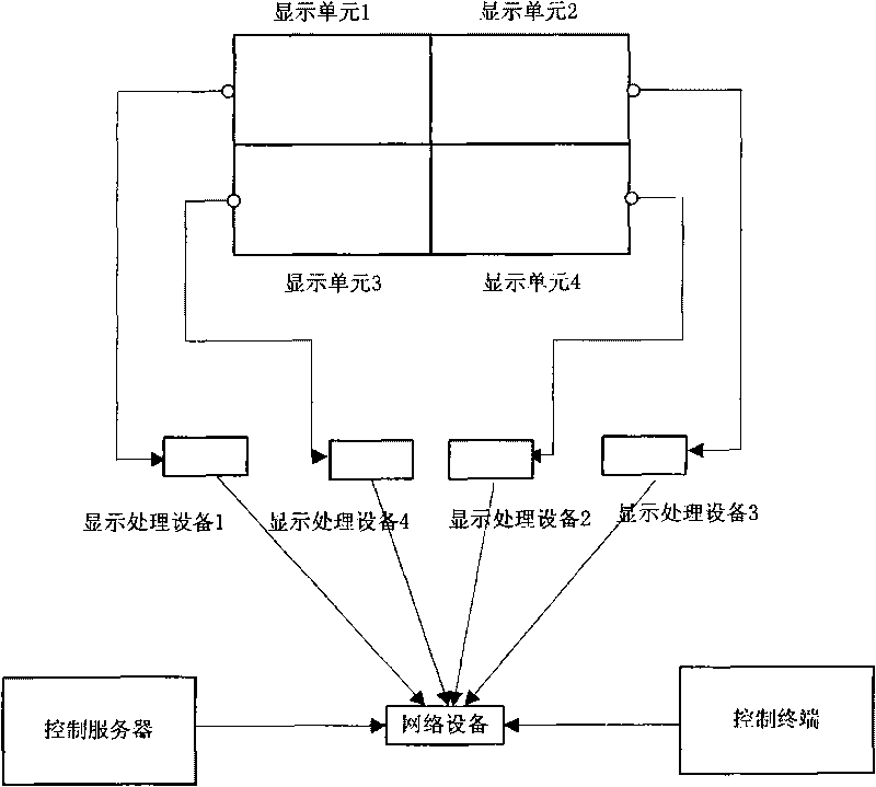
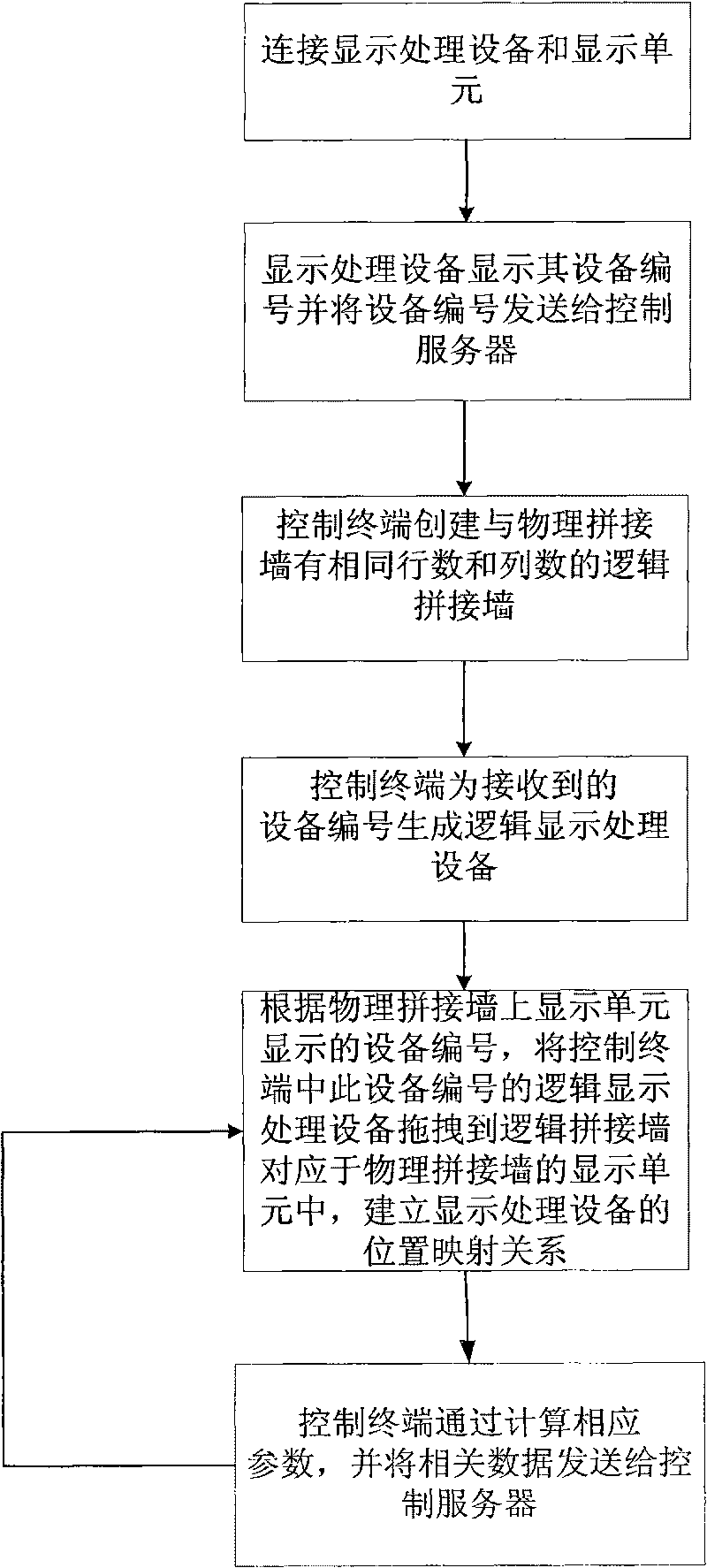
[0037] A configuration system for a mosaic wall, including a plurality of display processing devices and a plurality of display units corresponding to the display processing devices, and also includes:

[0038] The control server is used to receive the device number of the display processing device and send it to the control terminal, and receive and save the position mapping relationship of the display processing device sent by the control terminal;

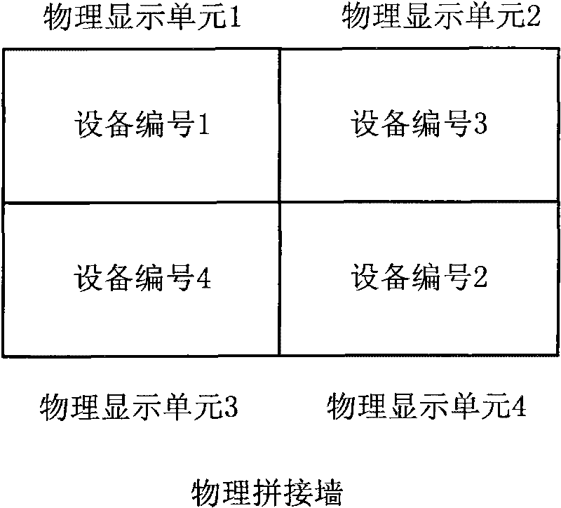
[0039] The control terminal is used to generate the corresponding logical display processing device according to the device number sent by the control server, and create a logical video wall corresponding to the physical video wall; according to the device number displayed by the display unit on the physical video wall, establish the display processing device The location mapping relationship is sent to the control server;

[0040] Such as figure 1 As shown, the control server, the control terminal and multiple display processi...

Embodiment 2

[0056] A configuration system for a mosaic wall, including multiple display units and more than one display processing device with multiple display output channels, and also includes:

[0057] The control server is used to receive the device number of the display processing device and the display output channel number and send them to the control terminal, and receive and save the position mapping relationship of the display processing device sent by the control terminal;

[0058] The control terminal is used to generate the corresponding logical display processing device according to the device number and display output channel number sent by the control server, and create a logical video wall corresponding to the physical video wall; according to the device number displayed by the display unit on the physical video wall, Display the output channel number, establish the position mapping relationship of the display processing device, and send it to the control server;

[0059]...


PUM


Abstract

The invention discloses a spliced wall body allocation system, comprising a plurality of display processing equipment, a plurality of display units, a control server and a control terminal; wherein, the control server and the control terminal are connected with a plurality of the display processing equipment networks, and the display processing equipment are connected with the display units. The invention also discloses a position mapping method for establishing display units by the system. In the method, the display processing equipment and the display units are connected in arbitrary consequences; the characteristic numbers of the display processing equipment are self-displayed; logical spliced walls corresponding to physical spliced walls and corresponding logical display processing equipment are established by the control terminal; the logical display processing equipment in the control terminal are dragged into the display units corresponding to the logical spliced walls according to the characteristic numbers on the physical spliced walls to establish position display relationships of the display processing equipment. The invention has the advantages of speediness, less workload and low cost.

Description

technical field [0001] The invention relates to the technical field of mosaic wall positioning, in particular to a configuration system of a mosaic wall and a position mapping method for establishing a display unit. Background technique [0002] In order to meet the needs of large-screen display in some special occasions, the splicing wall processing system came into being. The display unit of the splicing wall system can display and output a single screen to completely display a picture; it can also output multiple screens splicing, each display unit displays different parts of the signal source, and the images displayed by each display unit are spliced ​​into a complete display picture. Therefore, in order to realize correct multi-screen display, it is necessary to determine the position mapping relationship between each display unit. [0003] The Chinese patent application number is 200910132632.2, and the document titled "Position Mapping Method and Device of Display U...

Claims


Application Information

Patent Timeline
Patent Type & Authority Applications(China)
IPC IPC(8): G09G5/00G06F3/14
Inventor 谷新征谭建军刘先才冯海勇蔡才冠
Owner GUANGDONG VTRON TECH CO LTD
Why Eureka
Try Eureka