Supercharge Your Innovation With Domain-Expert AI Agents!

Cable pulling tool

A tool and cable end technology, applied in the direction of cable laying equipment, etc., can solve the problems of injury to construction personnel, cable damage, delay in construction, etc., and achieve the effect of improving safety factor and efficiency, increasing traction strength, and facilitating construction

Inactive Publication Date: 2010-06-30
SHANGHAI YALONG IND
View PDF0 Cites 0 Cited by
  • Summary
  • Abstract
  • Description
  • Claims
  • Application Information

AI Technical Summary

Problems solved by technology

However, when this kind of mesh is used for traction, the force-bearing part of the cable is mainly on the plastic sheath, so for ordinary cables, the traction strength is generally only 7N / mm 2 Below, even for high-voltage cables with greater traction strength, although the stress-bearing part can be on the aluminum sleeve or lead sleeve, the traction strength can only be 40N / mm 2 the following
[0003] However, in the construction of the cable site, due to the difference in the way of paying out the wire (such as hanging the wire upwards) or the influence of the inherent gravity and other (fault) friction of the cable in the wire, it is possible to exceed the above traction strength. , which will cause the cable to slip off and cause damage to the cable, and even accidents that injure the construction personnel. In severe cases, the construction may even be delayed.

Method used


Image

  • Cable pulling tool
  • Cable pulling tool
  • Cable pulling tool

Examples


Embodiment 1

[0013] Example 1 、Cable pulling tool suitable for YJV-8.7 / 10kV 3*240

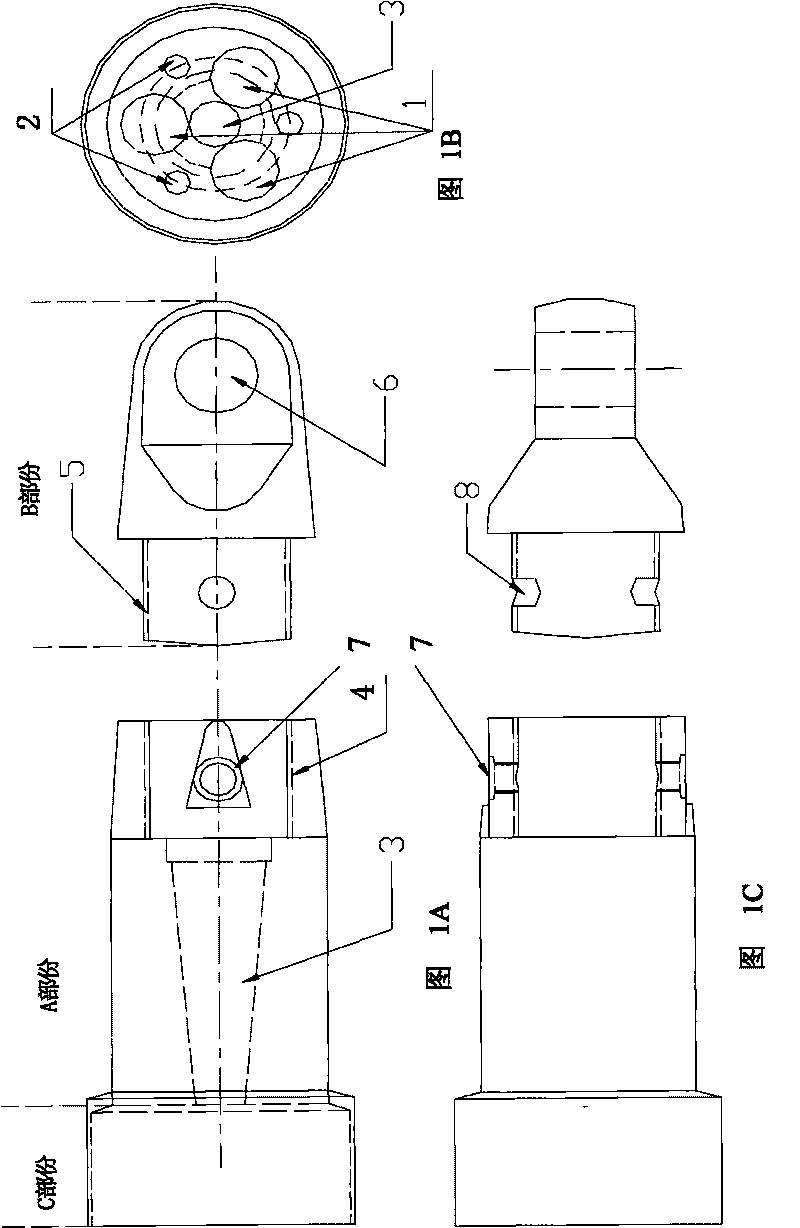
[0014] The structure of the cable pulling tool suitable for YJV-8.7 / 10kV 3*240, such as figure 1 As shown, it is mainly divided into three parts, namely the conductor expansion part A, the traction connection part B and the cable end protection part C, as follows:

[0015] Conductor expansion part A has a length of 140mm. According to the design expansion strength requirements, the outer diameter of part A is 72mm. The longitudinal direction of part A is uniformly arranged with three wire holes with an outer diameter of 18.4mm and a depth of 90mm. 1 (The center distance of the wire holes is set to 31.0mm according to the center distance of the insulated cores in the cable). There are three small round holes 2 with a diameter of 12mm and a depth of 90mm that are conducive to expansion joints distributed between the wire holes 1. The radius of the small end is 8.5mm (slightly smaller than the radius of the...

Embodiment 2

[0018] Embodiment 2, the use of cable pulling tools suitable for YJV-8.7 / 10kV 3*240

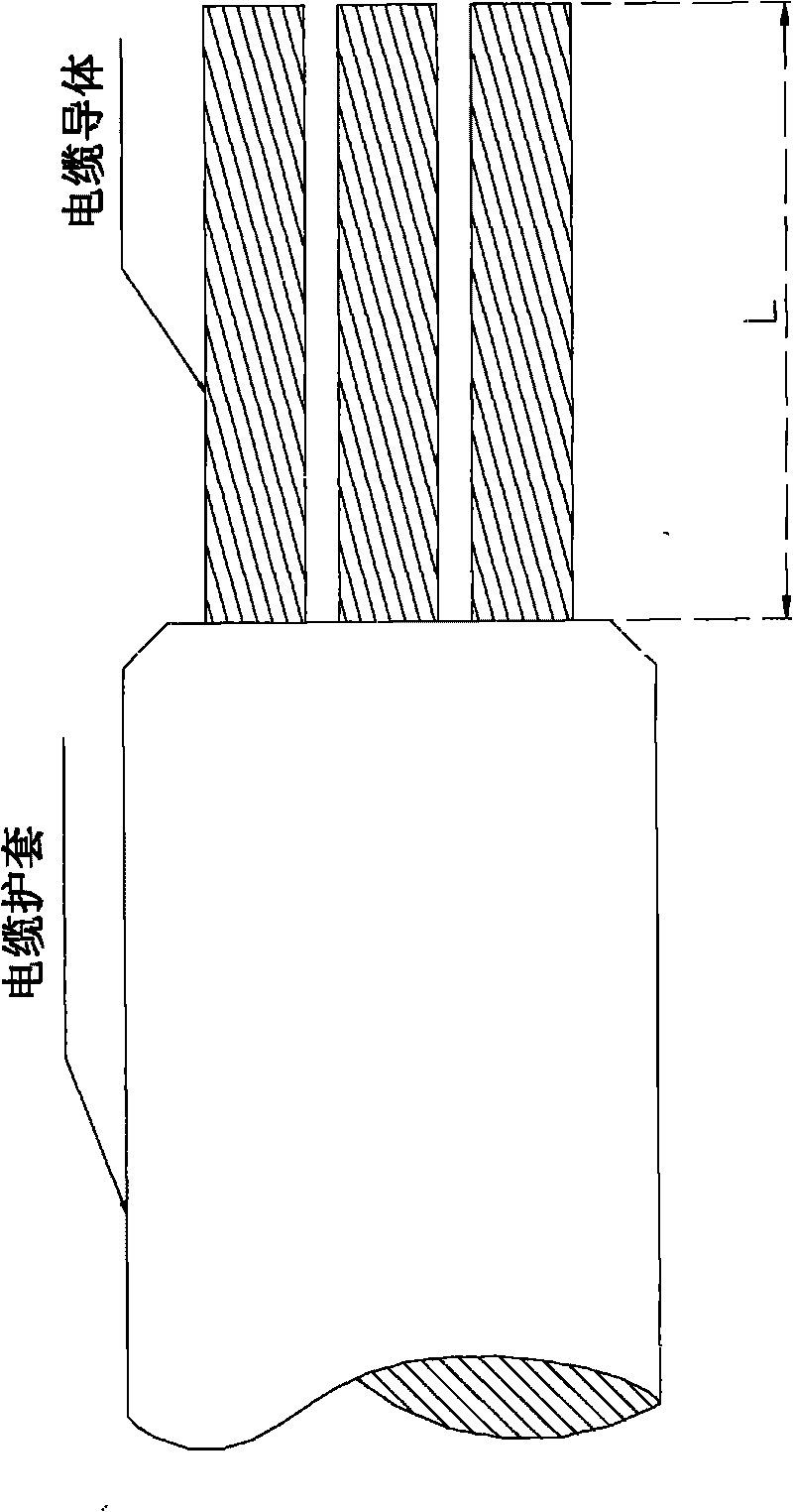
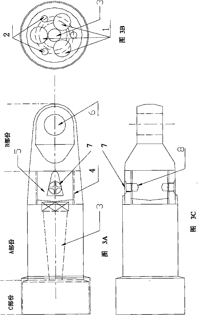
[0019] When in use, the outer diameter of the three-core cable whose outer diameter is slightly smaller than the inner diameter of the protective cover part C is as attached figure 2 Remove the material outside the conductor, the length L of the exposed part of the conductor in the figure is less than the attached figure 1 The depth of the middle wire hole 1 is 2~5mm. Insert the three core conductors into the wire hole 1 completely, and use the expansion screw to screw the expansion screw between the three conductors from the 4th end of the inner thread of part A to expand the conductor traction tool together, and then pass Thread to connect part A and part B, and then use countersunk screws to reinforce the connection between A and B through symmetrical countersunk screw holes 7 and light holes 8 (see the attached diagram for the combination diagram) image 3 ); the cable can be directly c...


PUM


Abstract

The invention provides a cable pulling tool. The tool comprises a conductor expansion connecting part and a pulling connecting part, wherein three screw holes are longitudinally and uniformly distributed on the conductor expansion connecting part; three small circular holes favorable for expansion connection are distributed among the screw holes; the center of the conductor expansion connecting part is provided with a tapered through hole and an internal thread, and the end of the tapered through hole is expanded to the internal thread; and the pulling connecting part is provided with an external thread and a through hole, wherein the external thread is matched with the internal thread. The invention provides another cable pulling tool which comprises a cable end protecting part with the inner diameter thereof the same with the outer diameter of the cable. The invention improves the safety coefficient and efficiency of cable construction.

Description

technical field [0001] The invention belongs to the field of cable construction, and in particular relates to a cable pulling tool. Background technique [0002] When the cable is mechanically laid at present, the traction tool used for the connection between the traction machine and the cable is mainly a cable traction net sleeve. However, when this kind of mesh is used for traction, the force-bearing part of the cable is mainly on the plastic sheath, so for ordinary cables, the traction strength is generally only 7N / mm 2 Below, even for high-voltage cables with greater traction strength, although the stress-bearing part can be on the aluminum sleeve or lead sleeve, the traction strength can only be 40N / mm 2 the following. [0003] However, in the construction of the cable site, due to the difference in the way of paying out the wire (such as hanging the wire upwards) or the influence of the inherent gravity and other (fault) friction of the cable in the wire, it is possi...

Claims


Application Information

Patent Timeline
Patent Type & Authority Applications(China)
IPC IPC(8): H02G1/06
Inventor 李斌鲁邦秀计初喜周行勇赵怀顺
Owner SHANGHAI YALONG IND
Features
  • R&D
  • Intellectual Property
  • Life Sciences
  • Materials
  • Tech Scout
  • Unparalleled Data Quality
  • Higher Quality Content
  • 60% Fewer Hallucinations
Learn More