Winding apparatus

A device, wire technology, used in the field of effectively winding coils

Inactive Publication Date: 2010-06-30
TOYOTA JIDOSHA KK
View PDF3 Cites 16 Cited by
  • Summary
  • Abstract
  • Description
  • Claims
  • Application Information

AI Technical Summary

Problems solved by technology

However, to improve manufacturing rates, non-circular coils must be wound at high speeds

Method used


Image

  • Winding apparatus
  • Winding apparatus
  • Winding apparatus

Examples


no. 1 example

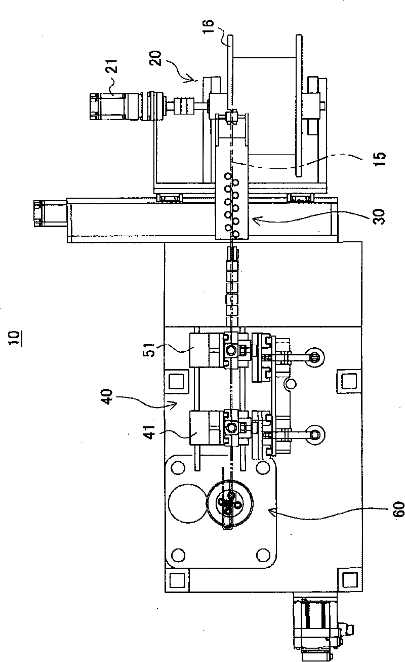
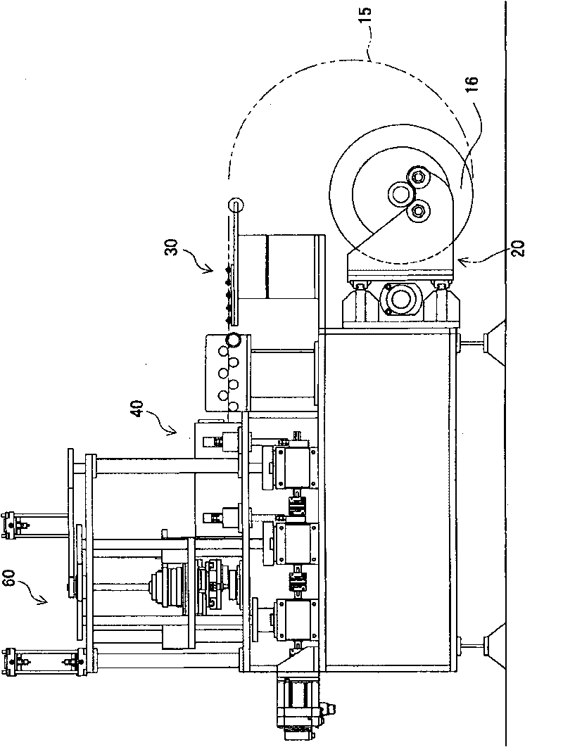
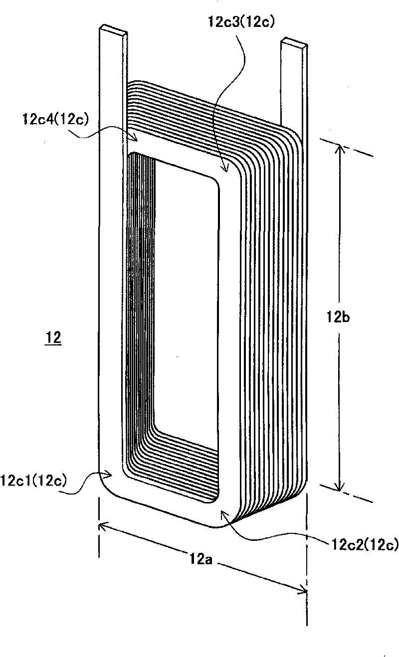
[0077] figure 1 is a plan view of the sidewinding apparatus 10 of the first embodiment. figure 2 is a side view of edgewise winding device 10 . image 3 is a perspective view of the coil 12 . exist figure 1 and figure 2 In , device 10 is partially omitted in terms of scale.

[0078] The edgewinding device 10 includes an uncoiler 20 , a straightening system 30 , a feeding system 40 and a bending system 60 . This apparatus 10 is configured to perform edgewise bending of a flat wire 15 , which is a conductor having a rectangular cross-section, to manufacture the coil 12 . Coil 12 is image 3 The coil is shown as being wound rectangularly, and includes a short side portion 12a and a long side portion 12b. These short side portions 12a and long side portions 12b correspond to non-curved portions existing between the curved portions 12c.

[0079] Each long side portion 12b has a length several times longer than each short side portion 12a. The bent portions 12c exist at f...

no. 1 example

[0160] The first embodiment providing the above configuration and operation specifically has the following advantages.

[0161] First, the coil 12 can be wound at high speed.

[0162] The edge bending apparatus 10 is configured to manufacture a coil 12 made by winding a flat wire 15 into a non-circular form by edge bending so that the coil 12 includes a plurality of bent portions 12c having equal bending angles, each existing in a bend Short side portion 12a and long side curved portion 12b between portions 12c. The apparatus 10 includes a holding shaft 67 to be brought into contact with the inner peripheral surface 15a of the flat wire 15 and to clamp the bent portion 12c of the flat wire 15 in the thickness direction of the flat wire 15, and a rotary table 75. The peripheral surface 15 a will form the inner periphery of the finished coil 12 . The apparatus 10 also includes a bending jig 77 to be brought into contact with the outer peripheral surface 15 b of the flat wire 1...

no. 2 example

[0173] The second embodiment is capable of performing the same operations as the first embodiment, except in the manner of power transmission. Configurations different from those of the first embodiment will be described below. Components or parts with the same symbols as those of the first embodiment have the same functions as those of the first embodiment. Figure 30 is a plan view of the edge-bending device 10 in the second embodiment. Figure 30 corresponds to figure 1 . Figure 31 is a side view of device 10 and corresponds to figure 2 .

[0174] The second embodiment is very different from the first embodiment in the way of power transmission. In the first embodiment, power transmission is performed through the roller gear 90 . On the other hand, in the second embodiment, power transmission is performed by the Malter mechanism to cause intermittent operation. Thus, the uncoiler 20 and straightening system 30 are substantially the same as the first embodiment.

...


PUM


Abstract

An edgewise winding apparatus (10) is arranged to produce a coil (12) by winding a wire (15). The coil (12) includes a plurality of bent portions (12c) having equal bending angles and unbent portions (12a, 12b) each existing between the bent portions (12c). The apparatus includes a holding shaft (67) which will contact with an inner periphery surface (15a) of a flat wire (15) and clamp one of the bent portions (12c) in a thickness direction of the flat wire (15) and bending jigs (77) which will contact with an outer periphery surface (15b) of the flat wire (15) and rotate while pressing the flat wire (15) in cooperation with the holding shaft (67) to bend the flat wire (15) to form the bent portion (12c). The bending jigs (77) are configured to move forward and backward in a lamination direction of the flat wire (15). The bending jigs are arranged in number equal to the number of bent portions (12c) or unbent portions (12a, 12b) of the coil (12) so that the bending jigs are placed at equal angular intervals around the holding shaft (67) so as to rotate around the holding shaft (67).

Description

technical field [0001] The present invention relates to a technique for efficiently winding a coil by using edge winding equipment. Background technique [0002] As a coil to be used in a rotating electric machine, there is a wound coil made of a rectangular cross-section flat wire in addition to a wound coil made of a circular cross-section wire. In order to increase the amount of current allowed to flow in the coil, the coil must be formed of thick wire. An increase in the cross-sectional area of ​​the wire tends to cause deterioration in the space factor of the wound coil made of a circular cross-section. On the other hand, a wound coil made of a rectangular cross-section is less likely to deteriorate the space factor even when the wire has a larger cross-sectional area. [0003] Hitherto, coils used in rotating electrical machines installed in vehicles have been required to be compact and have high performance. In particular, a rotating electric machine used in a vehi...

Claims


Application Information

Patent Timeline
Patent Type & Authority Applications(China)
IPC IPC(8): H02K15/04
CPCH01F41/065H02K15/045H01F41/071
Inventor 杉岛荣
Owner TOYOTA JIDOSHA KK
Why Eureka
Try Eureka