Cylindrical linear motor with double-layer air gaps

A linear motor, cylindrical technology, applied in the direction of electrical components, electromechanical devices, electric components, etc., can solve the problems of limiting system accuracy and dynamic response performance, error accumulation, inertia increase, etc., to improve winding utilization and effectively The effect of increasing the air gap area and increasing the thrust

Inactive Publication Date: 2010-07-07
HARBIN INST OF TECH
View PDF4 Cites 7 Cited by
  • Summary
  • Abstract
  • Description
  • Claims
  • Application Information

AI Technical Summary

Problems solved by technology

The existence of complex intermediate transmission mechanism causes problems such as error accumulation, ine...

Method used


Image

  • Cylindrical linear motor with double-layer air gaps
  • Cylindrical linear motor with double-layer air gaps
  • Cylindrical linear motor with double-layer air gaps

Examples


specific Embodiment approach 1

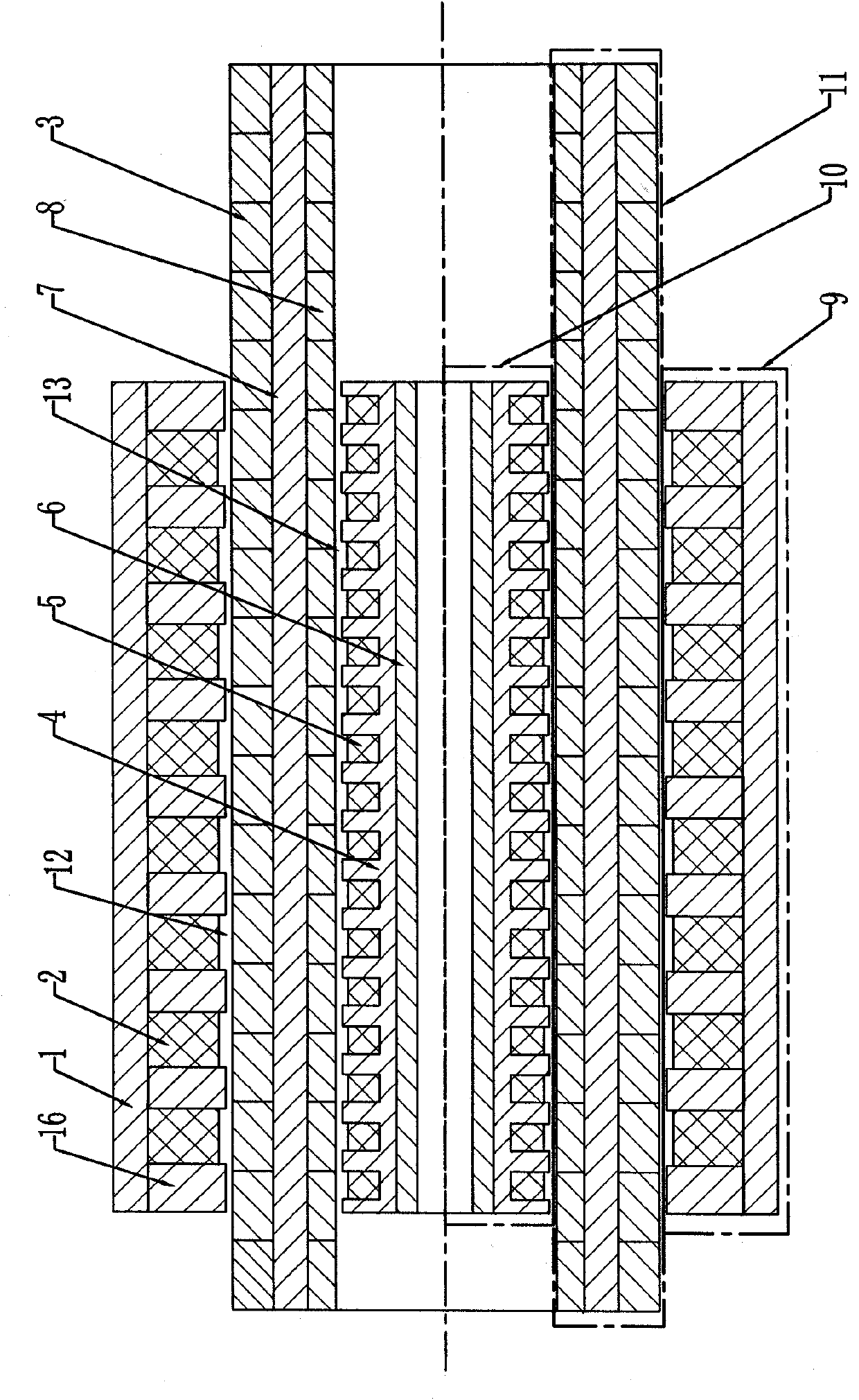
[0007] Specific implementation mode one: combine figure 1 , figure 2 and image 3 To illustrate this embodiment, the cylindrical linear motor of this embodiment is composed of an outer primary 9, an inner primary 10 and an intermediate secondary 11; the outer primary 9 is composed of a yoke 1, teeth 16 and an outer winding 2, and the yoke 1 It is a cylindrical magnetic core, and the teeth 16 are circular magnetic cores. The teeth 16 and the outer winding 2 are arranged at intervals on the inner wall of the yoke 1 along the moving direction of the motor rotor; the inner primary 10 is formed by the inner magnetic Core 4, inner layer winding 5 and non-magnetic shaft 6; non-magnetic shaft 6 is a cylindrical non-magnetic shaft, inner layer magnetic core 4 is the outer surface along the moving direction of the motor, and there are several The magnetically conductive core of the annular groove, the inner layer winding 5 is wound in the annular groove, the inner layer magnetically ...

specific Embodiment approach 2

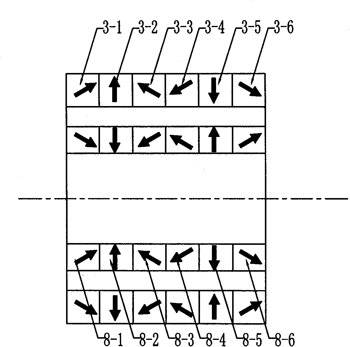
[0010] Specific implementation mode two: combination figure 2 Describe this embodiment, the difference between this embodiment and the specific embodiment is that the permanent magnets in the outer layer Halbach permanent magnet array 3 are evenly pasted on the outer surface of the middle permeable core 7, and every two adjacent ones along the axial direction The axial central axes of the permanent magnets coincide with each other, and the circumferential central axes of every two adjacent permanent magnets along the circumferential direction are located on the same circumferential line. Every pole of the outer layer Halbach permanent magnet array 3 has n permanent magnets. The magnetization directions of the permanent magnets located on the same axial central axis in the direction from left to right in each pole of the n permanent magnets are sequentially increased counterclockwise by α=180° / n angle. Other compositions and connection methods are the same as those in Embodime...

specific Embodiment approach 3

[0011] Specific implementation mode three: combination image 3 Describe this embodiment, the difference between this embodiment and the specific embodiment is that the permanent magnets in the inner layer Halbach permanent magnet array 8 are evenly pasted on the inner surface of the middle permeable core 7, and every two adjacent ones along the axial direction The axial central axes of the permanent magnets coincide with each other, and the circumferential central axes of every two adjacent permanent magnets in the circumferential direction are located on the same circumferential line, and each pole of the inner layer Halbach permanent magnet array 8 has m permanent magnets. The magnetization direction of the permanent magnets located on the same axial central axis in the direction from left to right in each pole of the m permanent magnets decreases in turn counterclockwise at an angle of β=180° / m. Other compositions and connection methods are the same as those in Embodiment ...


PUM


Abstract

The invention provides a cylindrical linear motor with double-layer air gaps, which relates to the field of motors and improves the volume space and the winding availability of the existing motor. Outer primary yokes are cylindrical magnetic conduction iron cores, outer primary teeth are annular magnetic conduction iron cores, and the teeth and outer windings are sequentially arranged on the inner walls of the yokes at intervals along the moving direction of a motor rotor; an inner primary non-magnetic conduction shaft is in a cylindrical shape, a plurality of annular grooves are sequentially formed on the outer surface of an inner primary magnetic conduction iron core at intervals along the moving direction of the motor rotor, inner primary windings are wound in the annular grooves, and the inner magnetic conduction iron core is sleeved on the non-magnetic conduction shaft; a middle secondary magnetic conduction iron core is in a cylindrical shape, and middle secondary outer and inner Halbach permanent magnet arrays are respectively pasted on the outer surface and the inner surface of the middle magnetic conduction iron core; and outer air gaps are formed between the outer primary magnetic conduction iron core and the middle secondary magnetic conduction iron core, and inner air gaps are formed between the inner primary magnetic conduction iron core and the middle secondary magnetic conduction iron core. The cylindrical linear motor is provided with the double-layer air gaps.

Description

technical field [0001] The invention relates to the field of linear motors, in particular to a cylindrical linear motor. Background technique [0002] Traditional linear motion is often realized by converting the rotary motion output by the rotary motor into linear motion through a ball screw pair and other intermediate transmission mechanisms. The existence of complex intermediate transmission mechanism causes problems such as error accumulation, inertia increase, vibration and noise, etc., thus limiting the accuracy and dynamic response performance of the system. Now, the direct transmission technology based on linear motion eliminates the intermediate complex transmission mechanism, and has been applied in linear motion occasions such as machine tools and elevators, and its application field is gradually expanding to various fields of production and life. Among them, the cylindrical linear motor has the advantages of high winding utilization rate, no transverse end windi...

Claims


Application Information

Patent Timeline
IPC IPC(8): H02K41/02
Inventor 李立毅黄旭珍曹继伟
Owner HARBIN INST OF TECH
Why Eureka
Try Eureka