Reflective cup set for light emitting diode (LED) lamp

A technology of LED lamps and LED lamps, applied in the field of reflector cups, can solve the problems of unsuitability for lighting systems, large divergence angles, and low energy of LED lights.

Inactive Publication Date: 2010-07-14
孙银焕
View PDF5 Cites 1 Cited by
  • Summary
  • Abstract
  • Description
  • Claims
  • Application Information

AI Technical Summary

Problems solved by technology

However, there are still many problems in the use of current LED lamps. The light energy of a single LED lamp is low and has a large divergence angle, which is not suitable for lighting systems alone.

Method used


Image

  • Reflective cup set for light emitting diode (LED) lamp
  • Reflective cup set for light emitting diode (LED) lamp
  • Reflective cup set for light emitting diode (LED) lamp

Examples


Embodiment 1

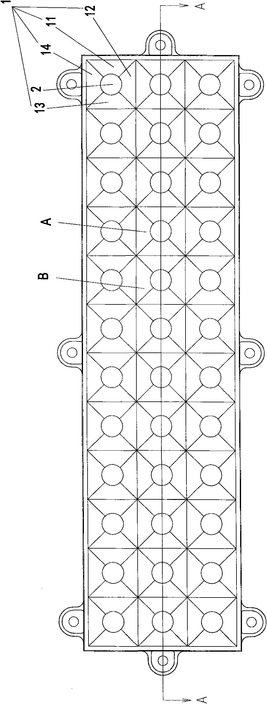
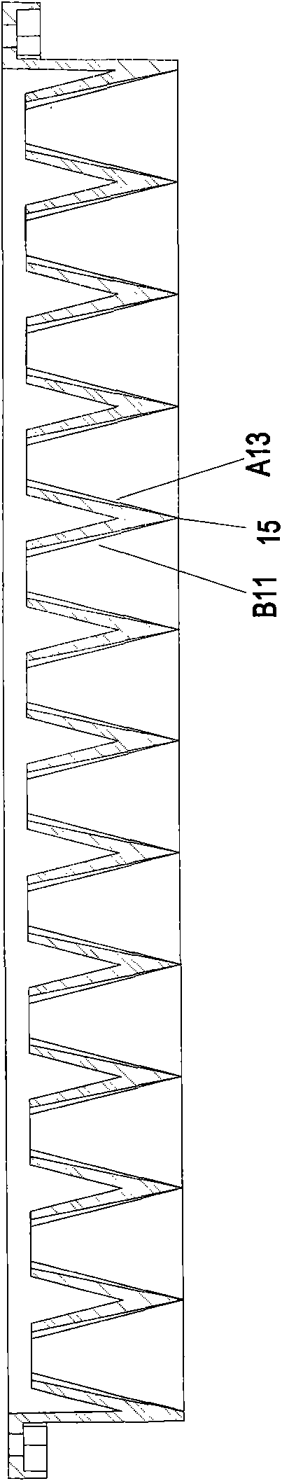
[0017] See figure 1 , figure 2 As shown, the reflective cup set of the LED lamp of the present invention is composed of thirty-six identical reflective cups. The thirty-six reflective cups are located in the same plane and are connected in series with each other. Prismatic, with four reflective surfaces, namely reflective surface 11, reflective surface 12, reflective surface 13, and reflective surface 14. The curvature of these four reflective surfaces is the same, and the curvature is determined according to the target plane and the position of the LED light. , the design curvature of each reflective cup ensures that the reflected light can reach the target plane, and the direct irradiation and reflected light are superimposed to make the target plane illuminate evenly; the LED light 2 is located in the center of the reflective cup cover body 1, and there is a The external reflective surface is connected, see figure 2 As shown, the reflective cup A is adjacent to the refl...

Embodiment 2

[0019] See image 3 , Figure 4 As shown, the reflecting cups of this reflecting cup set are not all in the same plane, and the shapes of the reflecting cups are also different. The curvature of each reflective surface in a reflective cup is also different. The shape and curvature of each reflective surface should be based on the actual situation. The design is determined, as shown in the figure, the reflective cup C is adjacent to the reflective cup D, and its reflective surface C11 is adjacent to the reflective surface D13. It is a straight edge. All the adjacent reflective surfaces of two adjacent reflective cups are close together to form a linear sharp edge to form a seamless whole. Since reflective cup C and reflective cup D are not in the same plane, reflective cup C and reflective cup D are not in the same plane. The shape of the reflecting cup D is different, such as Figure 4 As shown, the curved surfaces of the reflective surface C11 and the reflective surface D1...

Embodiment 3

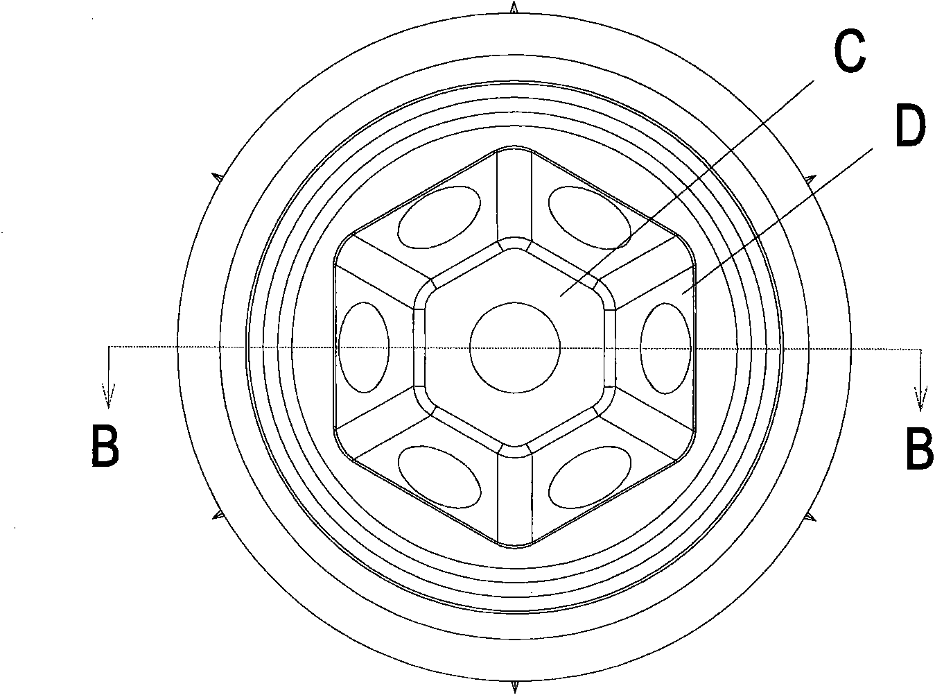
[0021] See Figure 5 , Image 6 As shown, it is composed of seven reflective cups. The seven reflective cups are located in the same plane. There are six reflective cup covers in the form of irregular quadrangular prisms, and one reflective cup cover E is in the shape of a regular hexagonal prism. The reflective cup E and The reflective cup F is adjacent, and its reflective surface E11 is adjacent to the reflective surface F13. The two reflective surfaces are close together to form a whole, and the end 17 thus formed is a straight-line sharp edge. All the adjacent reflective surfaces of two adjacent reflective cups are connected together to form a linear sharp edge so as to form a seamless whole.


PUM


Abstract

The invention relates to a reflective cup set for a light emitting diode (LED) lamp, mainly relates to the technical field of LED lamp illumination, in particular to the optical technical field of LED lamp reflective cups. The reflective cup set comprises a plurality of reflective cups, and is characterized in that the plurality of reflective cups are mutually connected in series, the reflecting surface of adjacent parts of two adjacent reflective cups lean against each other to form a whole, and the ends of the two adjacent reflective cups form a linear sharp edge. By adopting the structure, the plurality of reflective cups are connected in parallel to cover a target plane seamlessly, therefore, the reflective cup set uniformly illuminates the target plane and has high efficiency of light energy utilization.

Description

technical field [0001] The reflective cup set used for LED lamps of the present invention mainly relates to the technical field of LED lamp lighting, especially the technical field of LED lamp reflective cups and optics. Background technique [0002] As an emerging artificial light source, LED lights have shown excellent application prospects due to their small size, low energy consumption, and good monochromaticity. However, there are still many problems in the use of the current LED lamps. The light energy of a single LED lamp is low and has a large divergence angle, so it is not suitable for being used alone in a lighting system. When multiple LED lights are used together, it is necessary to consider the uniformity of light and the utilization rate of light energy, whether it can achieve uniform illumination of the target plane, and whether it can fully utilize the light of LED lights. Contents of the invention [0003] The object of the present invention is to provide...

Claims


Application Information

Patent Timeline
Patent Type & Authority Applications(China)
IPC IPC(8): F21V7/10F21Y101/02
Inventor 孙银焕
Owner 孙银焕
Why Eureka
Try Eureka